1I-14 Starting System:
2) Check continuity between terminal (2) and (3) each
time 12 V power supply is applied to terminal (4) and
(5).
Connect the positive (+) lead to terminal (5), and
negative (–) lead to terminal (4).
CAUTION
Be careful not to touch 12 V power supply
wires to each other or with other terminals.
Special tool
(A): 09930–99320 (Digital tester)
Tester knob indication
Continuity ( )
Starter motor relay function
3) Measure the resistance between relay terminals (4)
and (5).
If out of specification, replace starter motor relay.
Tester knob indication
Resistance (Ω)
Starter motor relay solenoid coil resistance
Standard: 145 – 190 Ω
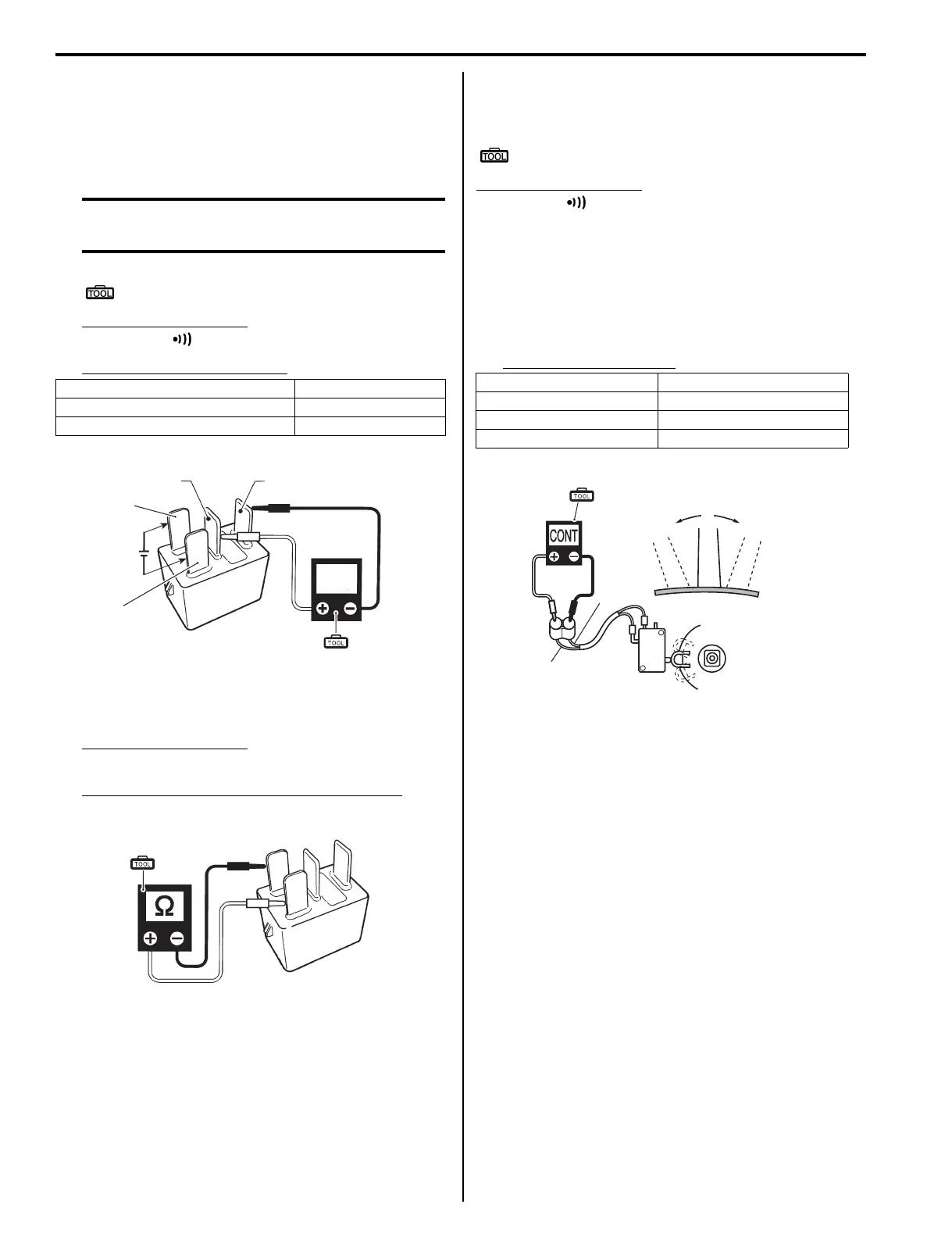
Neutral Switch Inspection
Z9J0111906008
Check for continuity / infinity of the neutral switch.
Special tool
(A): 09930–99320 (Digital tester)
Tester knob indication
Continuity ( )
Neutral switch in remo-con box
1) Disconnect the neutral switch lead wire connector
from the ignition switch.
2) Check continuity / infinity between the switch brown
wire leads while operating the remo-con handle.
If out of specification, replace the neutral switch.
Neutral switch function
Continuity
12 V power applied Yes
12 V power not applied No
CONT
12 V
2 3
4
5
(A)
I9J011190043-03
(A)
I9J011190044-02
Shift position Tester indicates
Neutral Continuity
Forward Infinity
Reverse Infinity
Br
Br
“Reverse” “Forward”
(A)
I9J011190045-03

 Loading...


