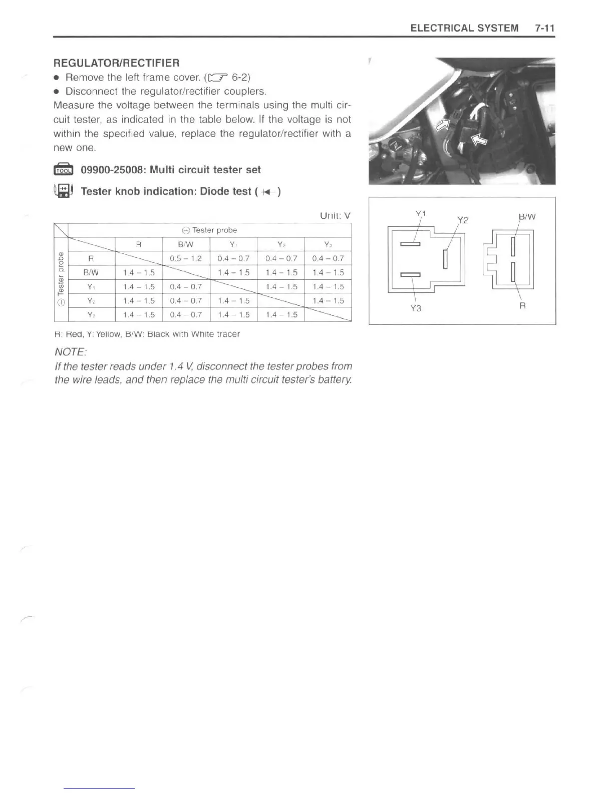
REGULATOR/RECTIFIER
• Remove the
left
frame cover.
(c::?
6-2)
• Disconnect the regulator/rectifier couplers.
Measure the
voltage between the terminals using the multi cir-
cuit tester, as indicated
in
the table below.
If
the voltage
is
not
within
th
e spec
ifi
ed value, replace the regulatorlrectifier with a
new one.
I§b 09900-25008: Multi circuit tester set
~
Tester knob indication: Diode test (
*-
)
"
e Tesler probe
----------
R
81W
y.
y,
w
R
---------
0.5 - 1.2 0,4 - 0.7
0,4
- 0.7
"'
e
"-
81W
1,4 - 1.5
-----------
1,4 - 1.5
1.4 - 1.5
*
y,
1.4 - 1
.5
0.4 - 0.7
-----------
1.4
-
1.5
~
----------
CD
y,
1,4 - 1.5 0,4 - 0.7 1.4 - 1.5
y ,
1.4 - 1.5
0.4 - 0.7 1.4 - 1.5 1.4 - 1.5
R:
Rea, Y:
YellOw
, BfW: Black. with White tracer
NOTE:
Unit: V
y,
0.4 - 0.7
1.4 - 1.5
1,4 -
1.
5
1,4-1.5
---------
If the tester reads under 1.4
V,
disconnect the tester probes from
the wire leads,
and
then replace the multi circuit tester's battery.
ELECTRICAL SYSTEM
7-11
BIW
Y3
R
http://www.motorcycle.in.th

 Loading...


