SIDE STAND/IGNITION INTERLOCK
SYSTEM PARTS INSPECTION
Check the
in
terlock system for proper operation.
If
the interlock
system does not operate properly, check each component for
damage or abnormalities.
If
any abnormality
is
found , replace
the component with a new one.
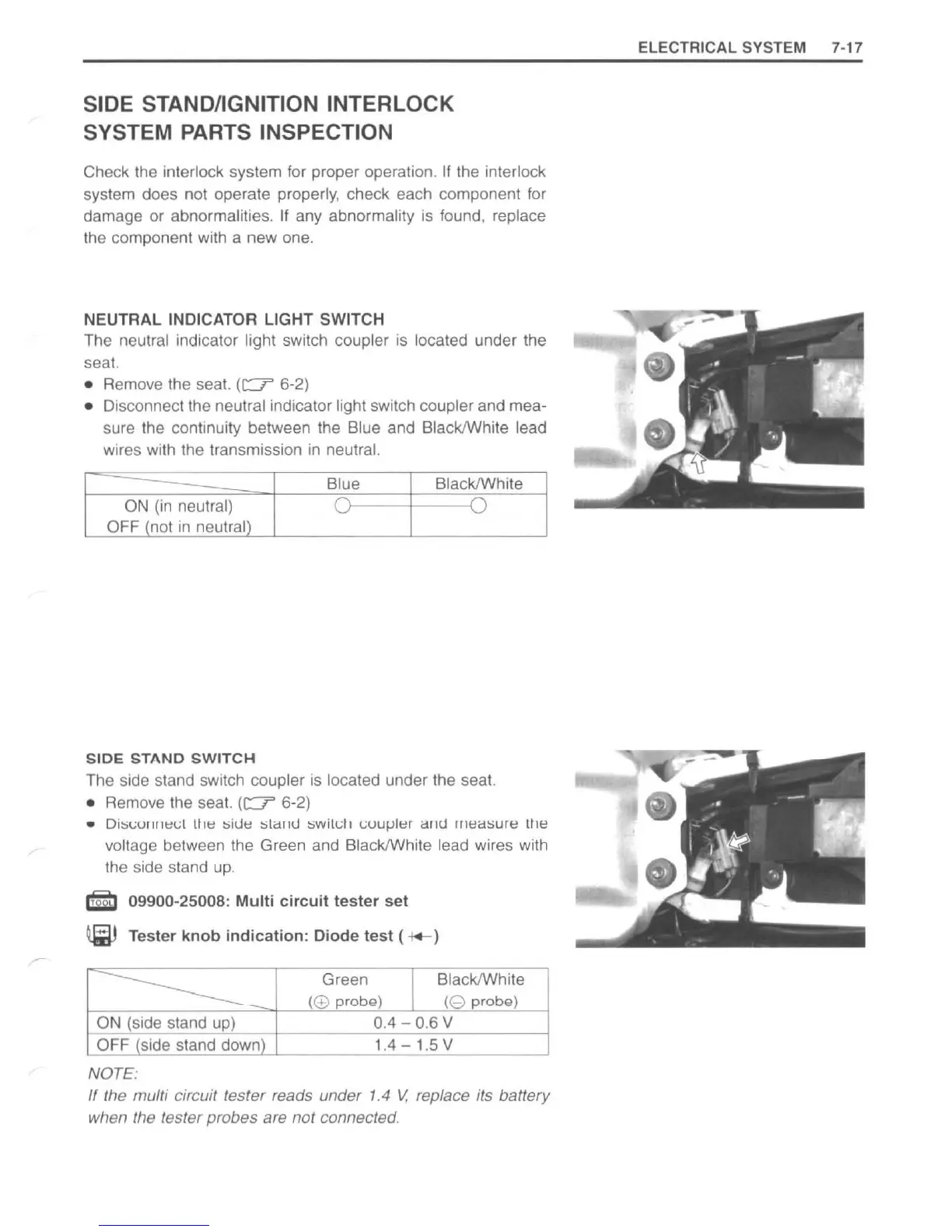
NEUTRAL
INDICATOR LIGHT SWITCH
The neutral indicator light switch coupler
is
located under the
seat.
• Remove the seat.
(c:?
6-2)
• Disconnect the neutral indicator light switch coupler and mea-
sure the continuity between the Blue and BlacklWhite lead
wires with the transmission
in
neutral.
Blue
BlacklWhite
ON
(in
neutral)
0 0
OFF (not
in
neutral)
SIDE
STAND
SWITCH
The side stand switch coupler
is
located under the seat.
• Remove the seat.
(c:?
6-2)
• Di:::il,;Ul1111:!t;1
tlrl:!
:siue
:sli::i
l
lU
:::;willJlr
L:uuJ-Ilt:n
cUHj
1rI1:!a.:::iure
ttH~
voltage belween Ihe Green and BlacklWhite lead wires with
the side stand
up.
!tEl
09900-25008:
Multi
circuit
tester
set
@ Tester
knob
indication
: Diode
test
( -t+- )
-----------
-
Green
I
BlacklWhite
(@
probg)
(8
probQ)
ON
(side stand
up)
0.4 - 0.6 V
OFF (side stand down) 1.4 - 1.5 V
NOTE:
If
the multi circuit tester reads under 1.4
V,
replace its battery
when the tester probes are
not
connected.
ELECTRICAL SYSTEM 7-
17
http://www.motorcycle.in.th

 Loading...


