7-
18
ELECTRICAL SYSTEM
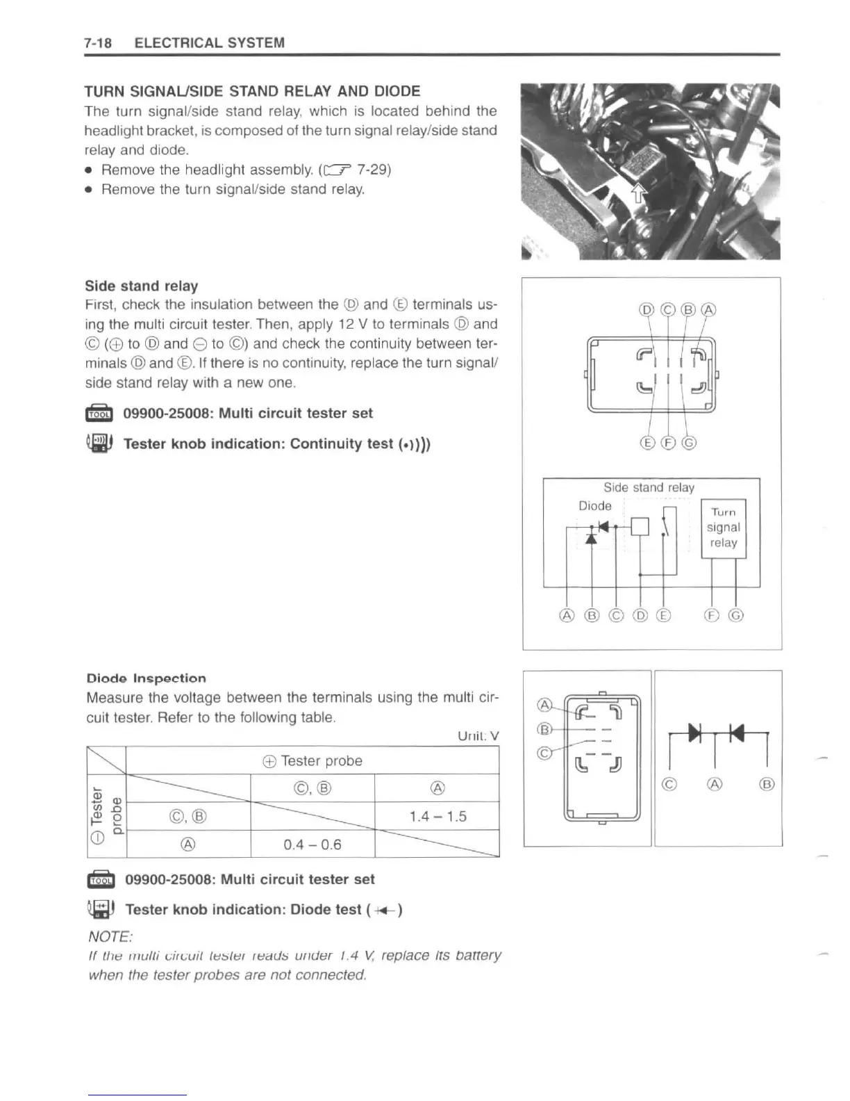
TURN SIGNAUSIDE STAND RELAY AND DIODE
The lurn signal/side stand relay, which is located behind the
headlight bracket,
is
composed
of
the turn signal relay/side stand
relay and diode.
• Remove the headlight assembly.
(c:::::r'
7-29)
•
Remove the turn signal/side stand relay.
Side stand relay
First, check the insulation between the (g) and
(g)
terminals us-
ing the multi circuit tester. Then, apply
12
V
to
terminals @ and
© (
(±)
to @ and e to ©) and check the continuity between ter-
minals
@ and
®.
If
there
is
no continuity, replace the turn signal/
side sta
nd
relay with a new one.
em
09900-25008:
Multi
circuit
tester
set
~
Tester
knob
indication:
Continuity
test
(_11)1
Diodo
In~pgction
Measure the voltage between the terminals using the multi cir-
cuit tester. Refer to the following table.
Unit:
V
~
(±)
Tester probe
2
Q)
-----
©,@
®
<JJ.o
©,@
----------
1.4 - 1.5
~
e
CD
0.
®
0.4 - 0.6
-------=
em
09900-25008:
Multi
circuit
tester
set
~
Tester
knob
indication:
Diode test
(*-)
NOTE:
/I
{he
multi
c'il(;ui{
{tI,;{tlr
ItldU,; uIIUer 1.4
V.
replace
Its
oattery
when the tester probes are not connected.
Side stand relay
Diode
r-
Turn
....
signal
L
rl
relay
I--
®@©@®
®@
(A)..
~'\)
I
~
[14
a -
I
©-
....---
~
.!J
© ®
@
http://www.motorcycle.in.th

 Loading...


