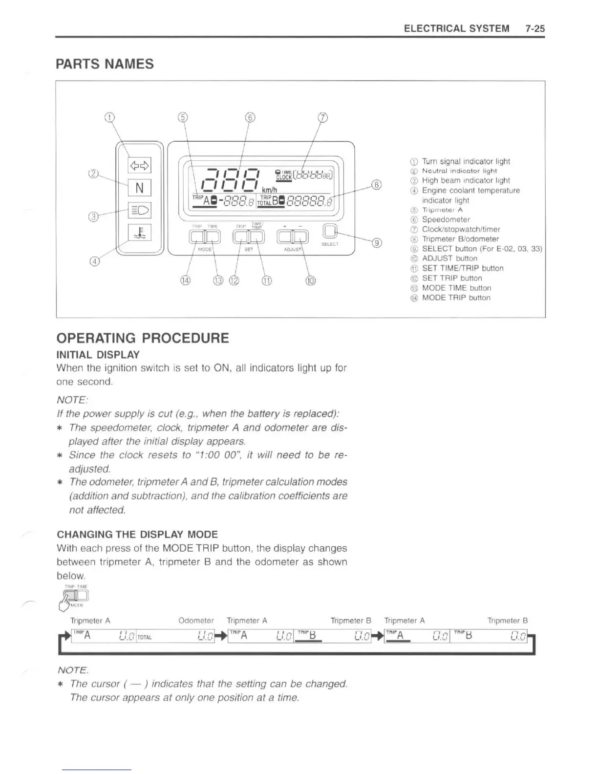
PARTS NAMES
5
4
-,,-,,-,
111111
1fliP
T'~'E
OPERATING PROCEDURE
INITIAL DISPLAY
7
Q
IIMt(
-1
"1.1
II
'001
~
OOOO
~J
SELECT
When the ignition switch
is
set
to
ON, all indicators light
up
for
one second.
NOTE
:
If
the power supply is cut
(e,g"
when the battery
is
replaced):
*
The
speedometer, clock, tripmeter A
and
odometer are dis-
played after the initial display appears,
* Since the clock resets to
"1
:00
00"
, it will need to be re-
adjusted,
*
The
odometer, tripmeter A
and
B,
tripmeter calculation modes
(addition and subtraction),
and
the calibration coefficients are
not affected,
CHANGING THE DISPLAY MODE
With each press
of
the MODE TRIP button, the display changes
between tripmeter A, tripmeter B and the odometer as shown
below.
8
9
ELECTRICAL SYSTEM 7-
25
Q)
Turn
signal
Indicator
light
@
Neutral
Indicator
light
G)
High
beam
Indicator
light
@
Eng
ine
coolant
temperature
Indicator
Ilghl
@
TI
1~lllcleli
A
® Speedometer
CD
Clock/stopwatch/timer
® Tripmeter B/odometer
® SELECT button (For E-02, 03,
33)
@ ADJUST button
® SET TIMEfTRIP button
@ SET TRIP button
@ MODE TIME button
® MODE TRIP button
Tnpmeter
A Odometer
Tnpmeter
A
Tripmeter
B Tnpmeler A
Tnpmeter
B
mflo~----'L'~~C
T
r-m-~--------'L'~~c
r.r'M"~A
'----'
L
~
~
~c~,·
~M"~
H'------'
L~c
~a
r.r
.M"~A
'----'
L~~~
c~,·~M"~
H'-
-----'
L
~
~~c
NOTE.
*
The
cursor (
--
) indicates that the setting can be changed,
The
cursor appears
at
only one position at a time,
http://www.motorcycle.in.th

 Loading...


