ELECTRICAL SYSTEM 6-13
SLIP RINGS
If the slip rings are dirty, polish them with #400 sandpaper and
wipe them using a clean, dry cloth.
Then, measure the slip ring O.D. using vernier calipers. If it is less
than the service limit, replace the slip rings with new ones.
##
##
# 09900-20102: Vernier calipers (200 mm)
$$
$$
$ Slip ring O.D.
Service Limit: 14.0 mm
CARBON BRUSHES
Measure the length of the carbon brushes as shown. If the mea-
surement is less than the service limit, replace the carbon brushes
with new ones.
##
##
# 09900-20102: Vernier calipers (200 mm)
$$
$$
$ Brush length
Service Limit: 4.5 mm
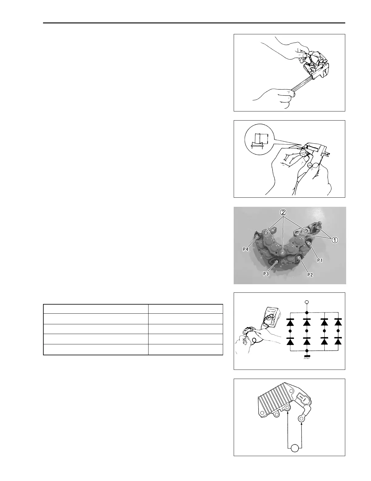
RECTIFIER
Measure the voltage among the terminal 1 and the other termi-
nals (P1, P2, P3 and P4). Put the tester lead on the terminal 1
and the other lead to P1, P2, P3 and P4 terminals. Observe the
reading and then switch the leads. Perform other side tests among
the terminal 2 and the other terminals (P1, P2, P3 and P4), as
described below. If the voltage measured is excessively out of
specification, replace the rectifier.
##
##
# 09900-25008: Multi circuit tester set
++
++
+ Tester knob indication: Diode test (
,,
,,
,)
IC REGULATOR
Measure the continuity between terminal “F” and terminal “B”.
There should be continuity in only one direction.
F : Rotor coil terminal
B : Battery terminal
##
##
# 09900-25008: Multi circuit tester set
))
))
) Tester knob indication: Continuity test (
**
**
*)
P1
P2
P3
P4
1
2
F
B
k Ω
Terminal – Terminal Voltage
1 - — + P1, P2, P3, P4 0.4 – 0.5 V
P1, P2, P3, P4 - — + 1 1.4 – 1.5 V
2 - — + P1, P2, P3, P4 1.4 – 1.5 V
P1, P2, P3, P4 - — + 2 0.4 – 0.5 V

 Loading...


