2-26
CONTROLS
SWITCHES
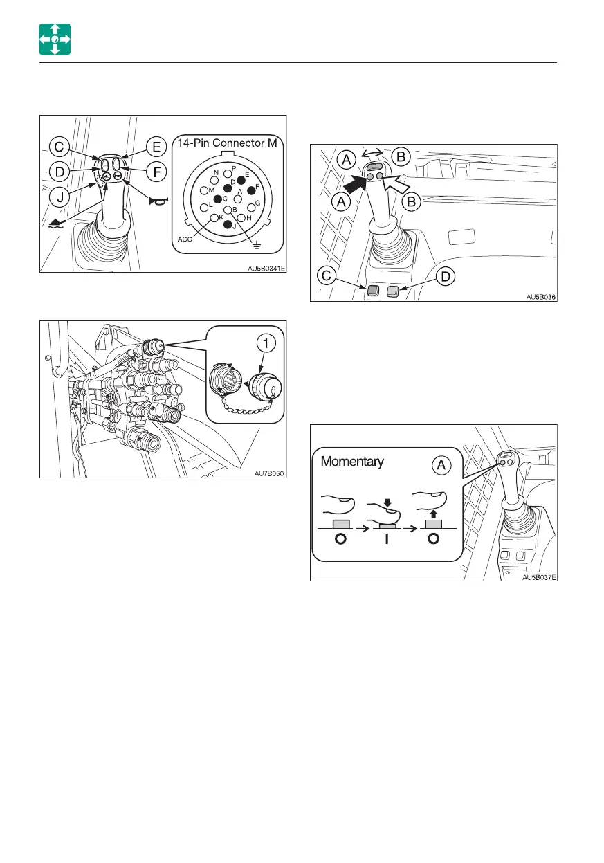
AUXILIARY HYDRAULIC SWITCHES
Auxiliary hydraulic buttons (A), (B)
Press auxiliary hydraulic buttons (A) or (B) to
control the flow of the oil in the auxiliary
hydraulic circuit.
(A) .......Hydraulic oil flows to auxiliary
hydraulic line (a)
(B) ......Hydraulic oil flows to auxiliary
hydraulic line (b)
These switches stay on while the buttons are
pressed; they turn off when the buttons are
released (momentary mode).
Note that the switch (A) can be also operated
in the detent mode, in which the switch state
alternates between “ON” and “OFF” every
time the button is pressed. To switch to the
detent mode, use the detent mode switch
(D).
If the selector switch (C) has been turned on
to select the one-way oil flow, only the switch
(A) can be used.
(A) .......Hydraulic oil flows to auxiliary
hydraulic line (a)
The return oil returns to the hydraulic tank
through the line (b).
MULTIFUNCTION BUTTONS
These buttons are used to operate various
optional functions.
1. Turn the cap (1) counterclockwise and
remove it.
2. To install the female connector or the cap
(1), align the notches and turn it clockwise
to tighten.
<14-pin connector M>
HDB34-18-14PN-059
Total max. working current: 20 A
Max. working current at each terminal: 13 A
Note: The total max. working current value
includes the 14-pins (G) and (H).
 Loading...


