Maintenance—2465B/2467B Service
6019-04
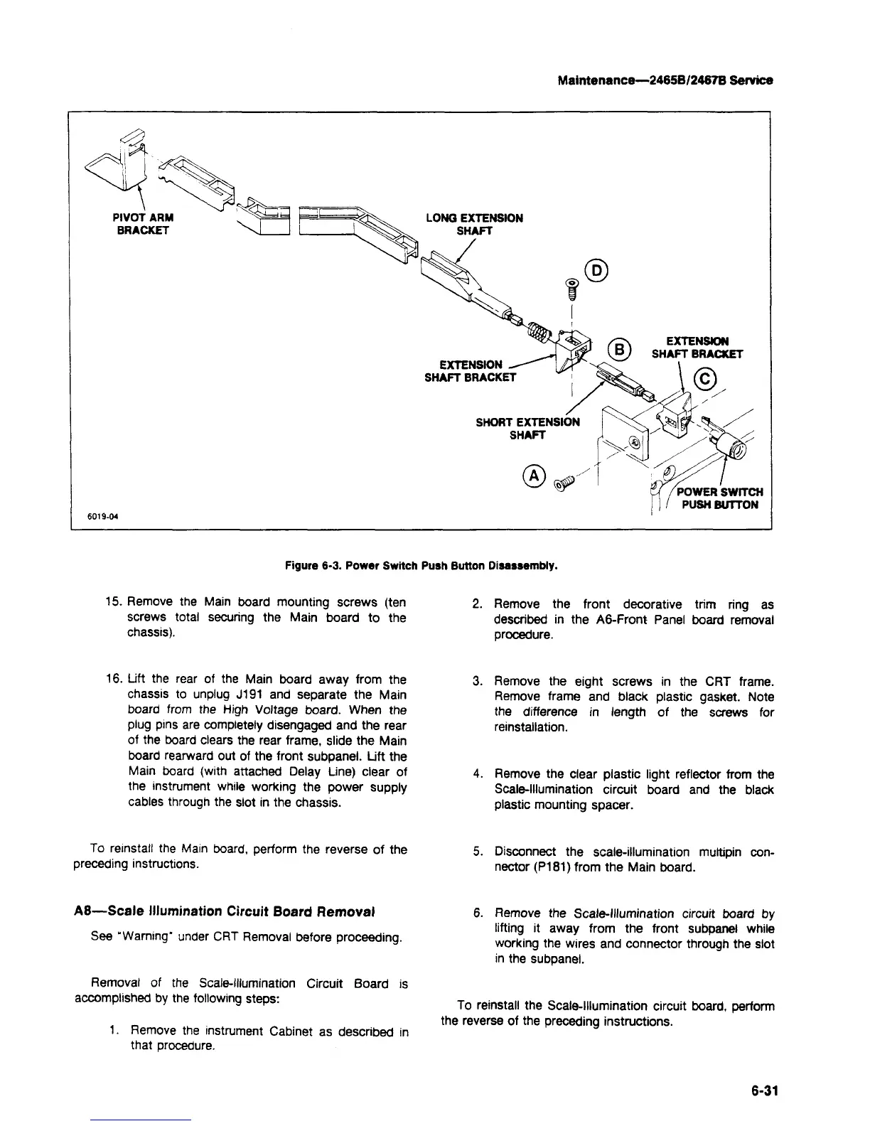
Figure 6-3. Power Switch
15.
Remove the Main board mounting screws (ten
screws total securing the Main board to the
chassis).
16.
Lift the rear of the Main board away from the
chassis to unplug J191 and separate the Main
board from the High Voltage board. When the
plug pins are completely disengaged and the rear
of the board clears the rear frame, slide the Main
board rearward out of the front subpanel. Lift the
Main board (with attached Delay Line) clear of
the instrument while working the power supply
cables through the slot in the chassis.
To reinstall the Main board, perform the reverse of the
preceding instructions.
A8—Scale Illumination Circuit Board Removal
See "Warning" under CRT Removal before proceeding.
Removal of the Scale-Illumination Circuit Board is
accomplished by the following steps:
1.
Remove the instrument Cabinet as described in
that procedure.
LONG EXTENSION
SHAFT
Button Disassembly.
2.
Remove the front decorative trim ring as
described in the A6-Front Panel board removal
procedure.
3. Remove the eight screws in the CRT frame.
Remove frame and black plastic gasket. Note
the difference in length of the screws for
reinstallation.
4.
Remove the clear plastic light reflector from the
Scale-Illumination circuit board and the black
plastic mounting spacer.
5. Disconnect the scale-illumination multipin
con-
nector (P181) from the Main board.
6. Remove the Scale-Illumination circuit board by
lifting it away from the front subpanel while
working the wires and connector through the slot
in the subpanel.
To reinstall the Scale-Illumination circuit board, perform
the reverse of the preceding instructions.
6-31