Reference
3-36
370B User Manual
The Step Generator provides current or voltage that can be applied to the base or
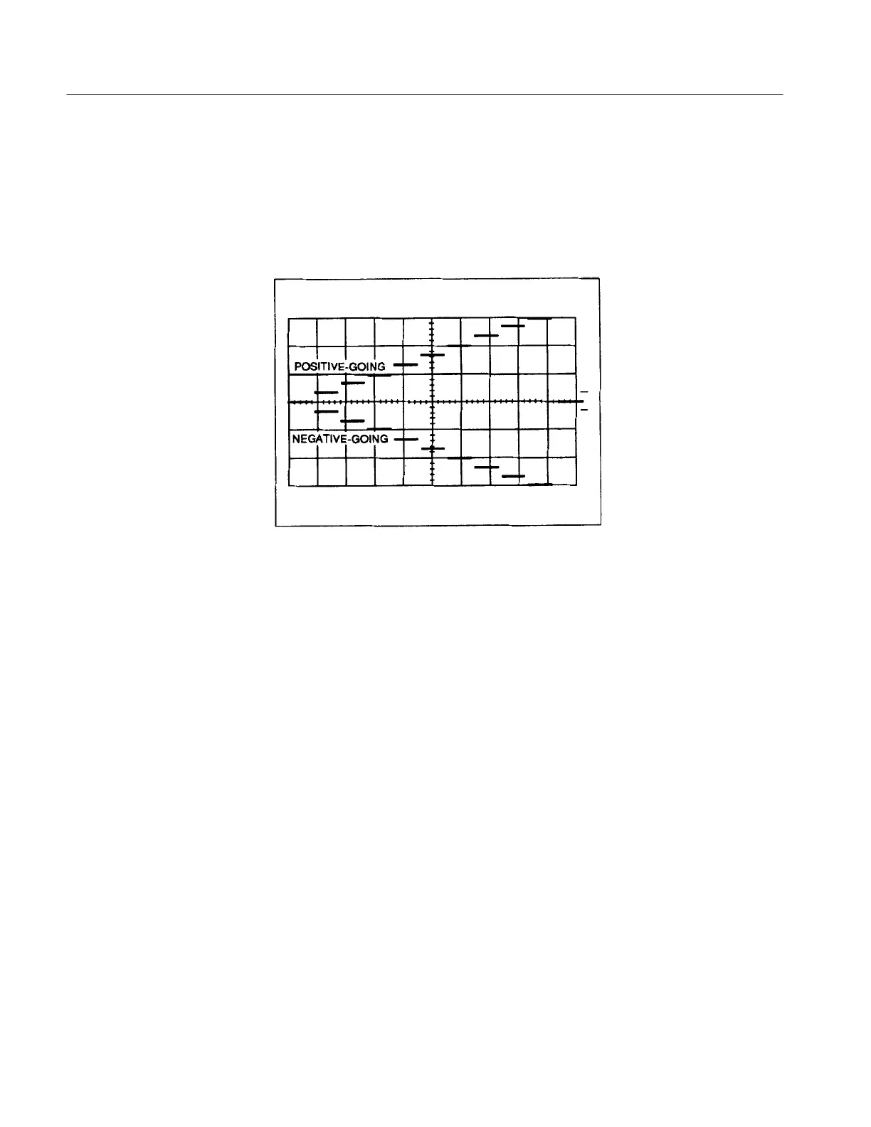
the emitter of the device under test. The output of the Step Generator is a family
of ascending steps of current or voltage (see Figure 3–23 ). When these steps
(together with the Collector Supply output) are applied to the device under test.
families of characteristic curves of the device are displayed on the CRT.
Figure 3-23: Step Generator output
The NUMBER OF STEPS controls determine the number of steps per family
and has a range of from 0 to 10 steps. VOLTAGE output or CURRENT output is
selected with the Output Mode Selection buttons. The AMPLITUDE control
determines the amplitude of each step. The range of step amplitudes available are
from 50 nA/step to 200 mA/step for current steps and from 50 mV/step to 2
V/step for voltage steps. Pressing the STEP MULTI.1X button divides the step
amplitude by 10. When voltage steps are being applied to the base of a transistor,
the base current increases very rapidly with increasing base voltage. To avoid
damage to the transistor when using voltage steps, current is limited by
current-limiting circuit.
The OFFSET buttons allow current or voltage to be either added or subtracted
from the Step Generator output. This causes the level at which the steps begin to
be shifted either in the direction of the ascending steps (aiding) offset or in the
opposite direction of the steps (opposing) offset. When the AID button and the
OPPOSE button are pressed simultaneously, the step offset return to zero. When
the AID button is pressed, current or voltage may be added to the Step Generator
output. The amount of current or voltage added to the Step Generator output
when the AID button is pressed is displayed at the OFFSET READOUT.
Pressing the OPPOSE button allows either current or voltage to be subtracted
from the Step Generator output, the amount subtracted from the Step Generator
output is displayed at the OFFSET READOUT.
Step Generator
 Loading...