Reference
3-35
370B User Manual
the graticule. When POLARITY is set to +
, the Collector Supply output is
a positive–going full–wave rectified sine wave. When POLARITY is set to
–
, the Collector Supply output is a negative-going full-wave rectified sine
wave. The AC position of the POLARITY provides a Collector Supply output
which is an unrectified sine wave. When POLARITY is set to +/– DC or
+/– LEAKAGE, the Collector Supply output is a DC voltage equal to the peak
voltage set by the MAX PEAK VOLTS controls and the VARIABLE COLLEC-
TOR SUPPLY control. This DC voltage may be either positive or negative. The
DC mode is very useful when the normal display is exhibiting excessive looping.
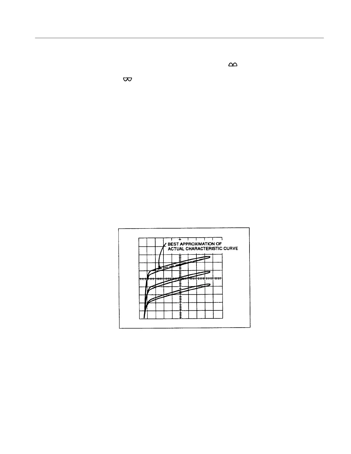
Occasionally some of the characteristic curves displayed on the CRT consist of
loops rather than lines (see Figure 3–22). This effect is called looping and is
most noticeable at very low or high current. Looping is usually caused by
internal stray capacitance or device capacitance, or by heating of the device
under test. The LOOPING COMPENSATION control provides complete
compensation for non heat-related looping. It does not compensate for any added
capacitance introduced by the device under test, only for internal and adapter
capacitance. (The control has some effect in reducing stray capacitance in small
diodes, and voltage–driven three–terminal devices.) If uncompensated looping
hinders a measurement, set the Collector Supply POLARITY to + DC or – DC
or use the SWEEP Measurement mode.
Figure 3-22: Display Looping
The 370B uses an interlock system. To use the 370B, the plastic protective cover
must be installed over the adapter connectors. When the protective box is in
place and the lid closed, the red WARNING indicator turns on. The red
WARNING indicator indicates that the Collector Supply is enabled and that a
dangerous voltage may appear at the front panel terminals.
Interlock System
 Loading...