Reference
3-34
370B User Manual
The stored sweep can then be reactivated at any time by pressing the Setup
RECALL button (with the Memory Index set to the proper location).
If the Display ENTER button is pressed during the sweep, all data captured up to
that point is stored in mass storage and the sweep continues.
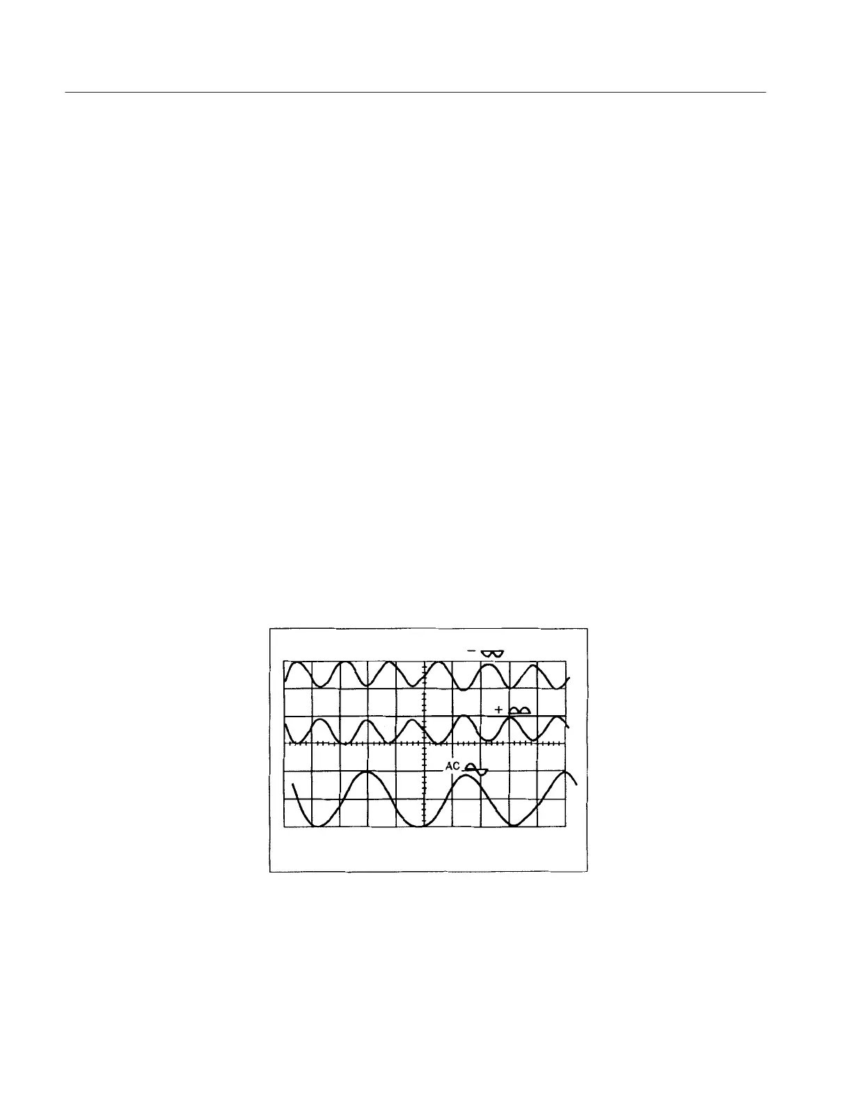
The Collector Supply provides operating voltage for the device under test. The
voltage is either a sine wave or a full-wave rectified sine wave (see Figure 3–21).
This voltage is applied to the front panel collector or base terminals.
The MAX PEAK VOLTS controls and the VARIABLE COLLECTOR SUPPLY
control determine the peak voltage output of the Collector Supply, which may be
varied from 0 volts to 2000 volts. The MAX PEAK VOLTS controls provide
four peak voltage ranges: 16 volts, 80 volts, 400 volts and 2000 volts. The
VARIABLE COLLECTOR SUPPLY allows continuous voltage variation of the
peak voltage within each peak voltage range. If the peak voltage range is
changed by the MAX PEAK VOLTS buttons, the Collector Supply output is
automatically reset to zero.
The MAX PEAK POWER WATTS controls determine the maximum power
output of the Collector Supply. Power output is controlled by placing a resistor,
selected from the SERIES RESISTORS , in series with the Collector Supply
output. The series resistance limits the amount of current that can be conducted
by the Collector Supply. In setting the peak power output using the MAX PEAK
POWER WATTS buttons, the proper series resistor is automatically selected.
Figure 3-21: Different Collector Supply Outputs.
The Collector Supply POLARITY controls determine the polarity and the type
of the Collector Supply output. They also provide an initial display position on
Collector Supply
 Loading...