!+)*#$* (%+()
!+)*#$* (%+()
5Ć16
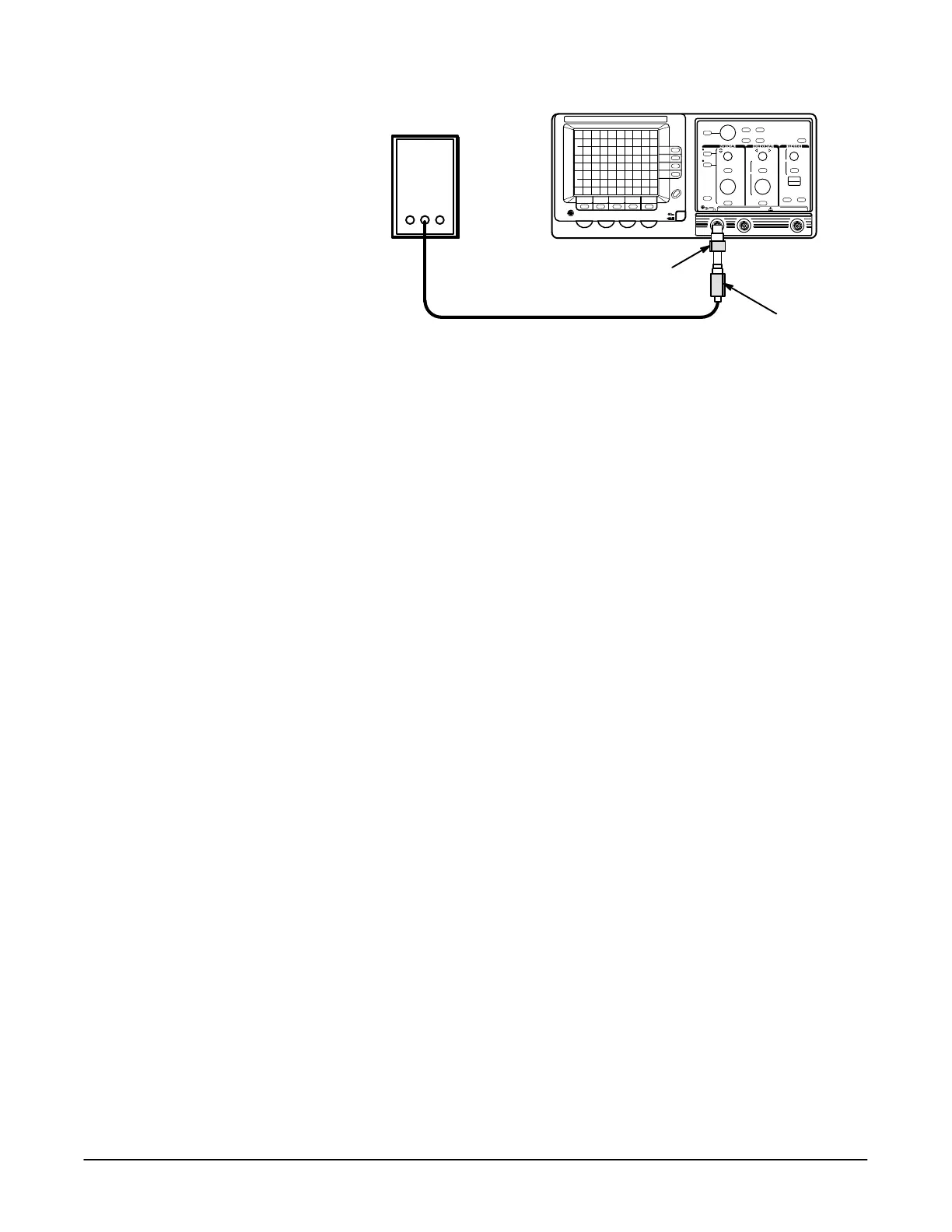
Pulse Generator
50 W Termination
Precision Cable
5X Attenuator
+( .- ('+$, *& )&%$) )* *+&
3. Set the pulse generator fast rise period to 1 ms and pulse amplitude to
midĆrange.
4. Press the button.
5. Set the volts/div scale to 10 mV.
6. Set the sec/div scale to 200 ns.
7. Press the button and set to .
8. Adjust the vertical control and the generator pulse amplitude
to obtain a 5 division, vertically centered, display.
9. $", Ċ Adjust R141 and C122 on the Display Driver board for
flattest long term response of the pulse front corner.
10. Set the sec/div scale to 20 ns.
11. Adjust R140 and C121 on the Display Driver board for minimum signal
aberrations of the pulse front corner.
NOTE
Some interaction of the adjustments made in steps 9 and 11 may
occur. For optimum oscilloscope performance, these steps should
be rechecked after making adjustments.
12. Disconnect the calibration setup from the oscilloscope.
**$+*%( %#&$)* %$
'+ &#$* '+ ( One pulse generator (item 10), one precision coaxial
cable (item 5), one 50 W termination (item 3), and one dualĆinput coupler
(item 7).
!+)*#$* %* %$) This procedure requires adjustments to the Analog
board. See Figure 5Ć15 on page 5Ć21 for the location of the adjustments.

 Loading...
