-%!" !-"*-()! $!&.
!-"*-()! !-%"%/%*)
4Ć4
0)/%*)' !./. -!-!,0%.%/!.
1. Power on the oscilloscope and allow a 20 minute warmĆup before perĆ
forming this procedure; adjust the control to display the
readout and the control to display waveforms.
2. Disable the dual delay with the following menu selections.
a. Press the button and select from the main menu.
b. Select until you can select 0' !'1 %.'! .
3. Press the button and set to "".
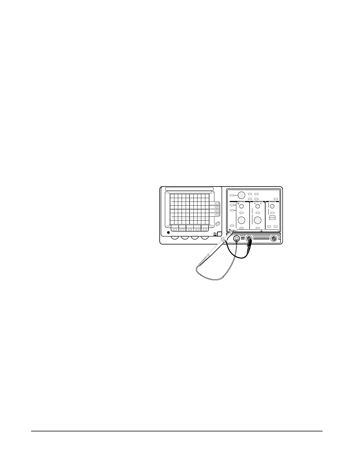
4. Install the probe on . Connect the probe tip to on
the frontĆpanel; connect the probe ground to the ground barrel of an
unused input BNC (see Figure 4Ć2).
Some functional checks require that you install the probe on connectors
other than . All functional checks use the on the
frontĆpanel as the signal source.
%#0-! 32!./ **&0+ "*- 0)/%*)' !./.
!-%"1 /$! -*! *(+!)./*- 0/+0/
1. Press the button until the readout indicates that only
channel 1 is selected.
2. Press the button.
3. Press the button and set to .
4. Set the volts/div scale to 1 V and vertically center the display.
5. Set the sec/div scale to 500 ms.
6. Press the button and set D to ).
7. Align the active cursor to the top of the signal using the General Purpose
Knob.

 Loading...
