Rev
A:
0611
5/98
"
TEIWTRWlC
CCRFOEATICN
Preparation
for
Use
TP04100A Interface
&
Applications
2-17.2
Standard Thermocouple Interfacing
2-1
7.2.1
Sensor Interface Guidelines
THERMAL CAP
\
1
THERMAL SHROUD
SENSOR CONNECTOR
IIIIIIIIIIIIIIIIIIIIIIII
[TO It0 PANEL) MODIFIED SOCKET
DLIT BOARD
1361
41
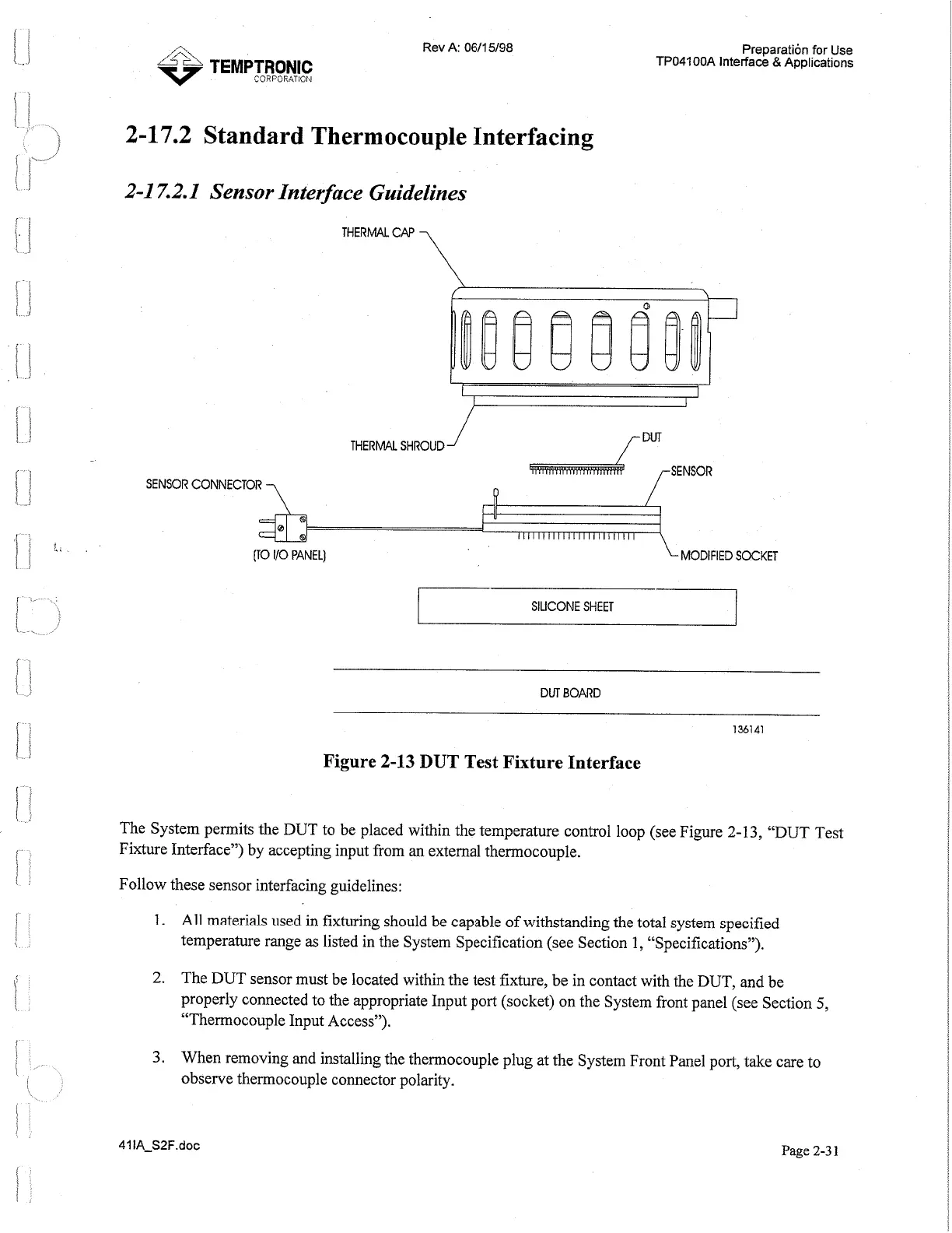
Figure
2-13
DUT
Test Fixture Interface
The System permits the DUT to be placed within the temperature control loop (see Figure
2-1
3, "DUT Test
Fixture Interface") by accepting input from an external thermocouple.
Follow these sensor interfacing guidelines:
All materials used in fixturing should be capable of withstanding the total system specified
temperature range as listed in the System Specification (see Section
1,
"Specifications").
The DUT sensor must be located within the test fixture, be in contact with the DUT, and be
properly connected to the appropriate Input port (socket) on the System front panel (see Section
5,
"Thermocouple Input Access").
When removing and installing the thermocouple plug at the System Front Panel port, take care to
observe thermocouple connector polarity.
41 IA-S2F.doc
Page
2-3
1
Artisan Technology Group - Quality Instrumentation ... Guaranteed | (888) 88-SOURCE | www.artisantg.com
 Loading...