;A
4b
T7
TEMPTRONIC
ZOPC~FPTIJI
I
3-6
Local
Operation
Rev A:
0611
5/98
System Operation
TPO4100A
Interface
&
Applications
3-6.1
Startup
by
Power
ON
MAIN POWER
SWITCH
7
t',
POWER INDICATOR LAMP
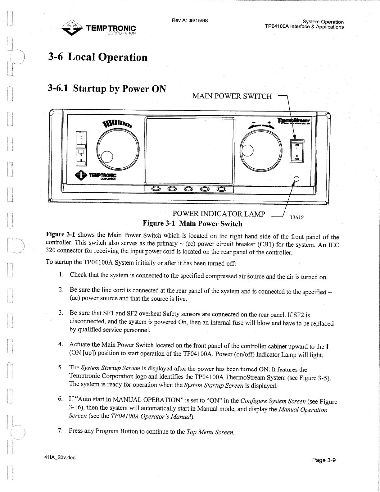
Figure
3-1
Main Power Switch
Figure
3-1
shows the Main Power Switch which is located on the right hand side of the front panel of the
controller. This switch also serves as the primary
-
(ac) power circuit breaker (CBI) for the system. An IEC
320 connector for receiving the input power cord is located on the rear panel of the controller.
To startup the TP04100A System initially or after it has been turned off:
Check that the system is connected to the specified compressed air source and the air is turned on.
Be sure the line cord is connected at the rear panel of the system and is connected to the specified
-
(ac) power source and that the source is live.
Be sure that SF1 and SF2 overheat Safety sensors are connected on the rear panel. If SF2 is
disconnected, and the system is powered On, then an internal fuse will blow and have to be replaced
by qualified service personnel.
Actuate the Main Power Switch located on the front panel of the controller cabinet upward to the
1
(ON [up]) position to start operation of the TP04100A. Power (onloff) Indicator Lamp will light.
The
System Startup Screen
is displayed after the power has been tumed ON. It features the
Temptronic Corporation logo and identifies the TP04 100A ThermoStrearn System (see Figure
3-5).
The system is ready for operation when the
System Startup Screen is
displayed.
If "Auto start in MANUAL OPERATION" is set to "ON in the
Configure System Screen
(see Figure
3-16), then the system will automatically start in Manual mode, and display the
Manual Operation
Screen
(see the
TP04100A
Operator's Manual).
Press any Program Button to continue to the
Top Menu Screen.
Page
3-9
Artisan Technology Group - Quality Instrumentation ... Guaranteed | (888) 88-SOURCE | www.artisantg.com
 Loading...