6
6-21
4st 4/5/6 2011
2
1
1
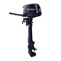
Backlash Measuring Tool Kit :
P/N. 369-72740-0
Backlash Measuring Tool Ass’y 1 :
P/N. 369-72730-0
Measuring Tool Set Piece 2 :
P/N. 369-72727-0
Clamp A :
P/N. 3B7-72720-0
Dial Gauge Plate :
P/N. 3B7-72729-0
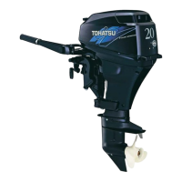
1. Install pump case 4 to gear case, and assemble backlash
measuring tool 1 as illustrated.
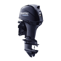
29) Determination of forward (A) gear
backlash
4 Pump Case
5 Pinion (B) Gear
Perform measurement of backlash between
forward (A) gear and pinion (B) gear with propeller
shaft housing, propeller shaft and reverse (C)
gear removed from gear case.
· Fix gear case with vice.
· Clean drive shaft with new rag before
assembling the tool.
· Assemble all parts of pump case except
impeller and key, and tighten to specified
torque.
· Perform measurement of backlash between
forward (A) gear and pinion (B) gear with
propeller shaft housing, propeller shaft and
reverse (C) gear removed from gear case.
Sizes of Adjusting Shims :
For Pinion (B) Gear Side : 0.1, 0.15mm
Proper Backlash Obtained from Gauge Reading :
0.16 - 0.49mm (0.0063 - 0.0193 in)
MFS4-5-6Ech06110422.qxd 11.4.22 5:50 PM ページ21

 Loading...