Startup
EN DE
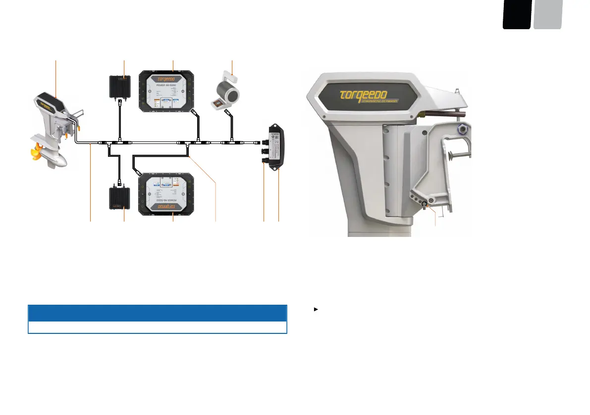
Fig. 42: Schematic arrangement of a TorqLink network with the 1949-1952 accelerator lever
1
Cruise 10.0 R (terminating resistor)
5
Terminator Single
2
Charger unit
6
ON/OFF switch
3
Power 48-5000
7
Branch line
4
1949-1952 accelerator lever
8
Backbone
ADVICE
The branch lines must not be sub-divided or extended.
5.5 Trimming the motor
Fig. 43: Securing cotter pin for trim rod
1
Securing cotter pin
Install the tilt switch for trimming the motor as follows:
1. Drill a suitable hole into the console.
For this, align to the reverse side of the tilt switch.
2. Locate the data cable in the position provided on the motor.
3. Attach the tilt switch in the cockpit.
The tilting mechanism allows the motor to be tilted.
page 79 / 113
 Loading...