491600XPi Series UPS Installation and Operation Manual – 60616-014
19.2 (Optional) External Two-Breaker Maintenance Bypass
The Two-Breaker MBS solution will allow the user to transfer the load between utility and inverter power sources without
interruption. When using an MBS, the utility and inverter waveforms must be identical so ONLY 240V input and output
operation is available for the 1600XPi in this conguration.
240V Wiring
The following connections must be made to the Utility Panel and the Load Panel. The Main UPS output is located on the
terminal block on the back of the UPS. (TB-4(X1) and TB-7(X3) 240 VAC.) Ensure the UPS voltage selector jumper is set
to 240 V.
MAIN
OUTPUT
UTILITY
PANEL:
SINGLE Φ
240V
L1
L2
N
G
LOAD
PANEL
L1
L2
N
G
UPS
L1
L2
G
X1
X3
N
G
MAINTENANCE
BYPASS
CBL1
CBL2
CBM1
CBM2
G
L1
L2
See the application instructions included with the External Maintenance Bypass Unit for wiring details.
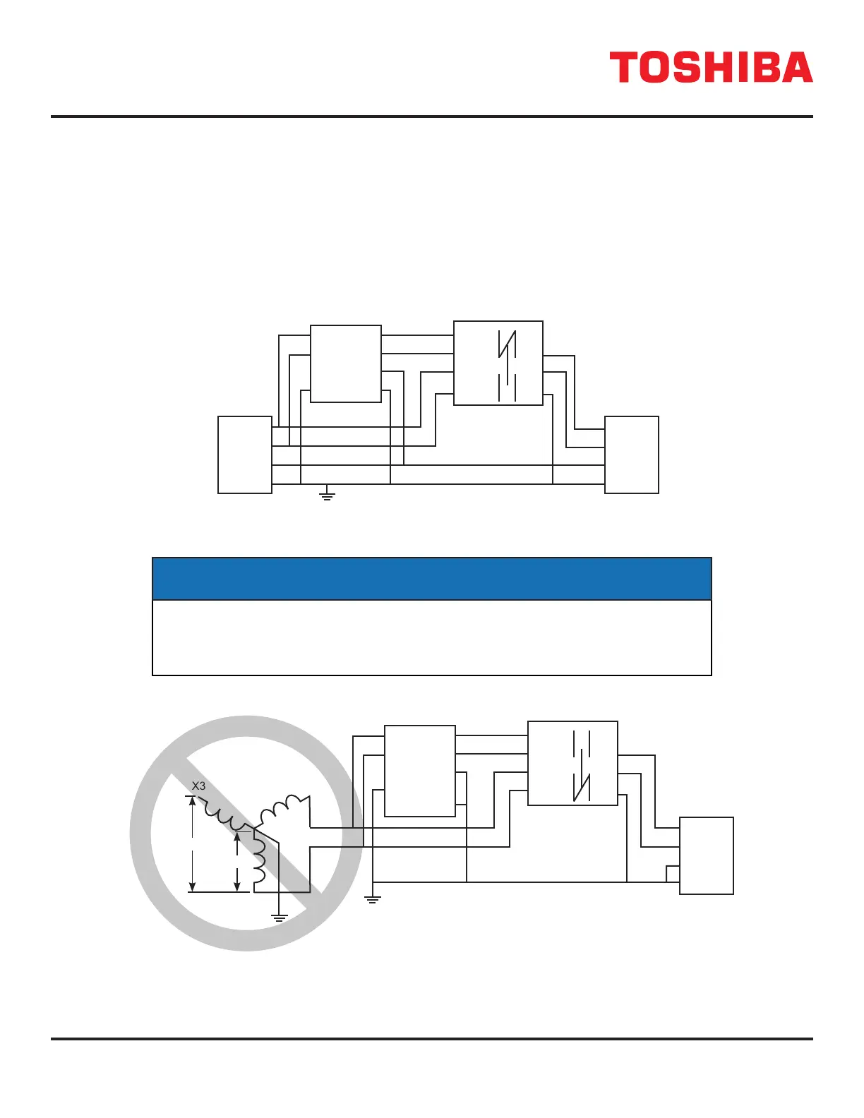
NOTICE
Do NOT use two legs of a three phase, 208/120V utility to feed the 1600XPi, as shown
below, if this external maintenance bypass is being used. The output of the UPS and
the utility feed have dierent phase to neutral references and transfer between the two
could cause loss of power or damage to the load.
MAIN
OUTPUT
UTILITY
PANEL:
3Φ
LOAD
PANEL
L1
L2
N
G
UPS
L1
L2
G
N
X1X3
X2
120V
208V
X2
X3
G
X1
N
MAINTENANCE
BYPASS
CBL1
CBL2
CBM1
CBM2
G
L1
L2
DO NOT USE 3-PHASE INPUT WHEN USING THIS EXTERNAL MAINTENANCE BYPASS
 Loading...