TOSHIBA
6.0 Functions
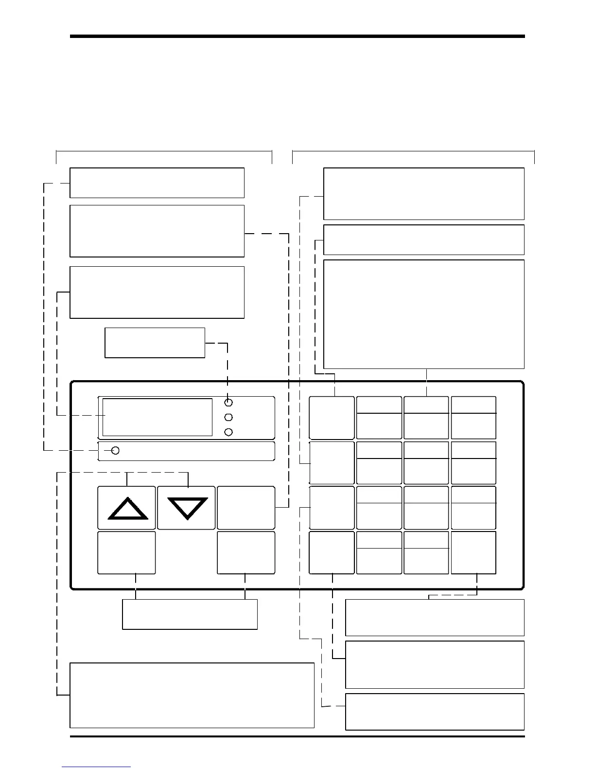
6.1 Operating Panel
The operating panel enables the user to run or stop (RUN/STOP) the inverter, read
and/or change the operating function parameter values (READ/WRT), and monitor
(MON/NEXT) the operating conditions of the unit (see key function section 6.5).
Operating Panel
6 - 1
PANEL CONTROL
Hz
SEC
%
RUN
CTRL
STOP
2ND
MON
CLR
NEXT
JMP TB SEL
7 98
OL REF JOG
V/F
4 5 6
1 2 3
FMAX READ
WRT
.0
RUN/STOP Keys used to
start and stop the inverter.
ACC/DEC
UL/LL
"UP"/"DOWN" scroll keys used for changing the
inverter's operating frequency and function parameter
settings. Can also be used, during special operations,
for engaging forward/reverse runs and for calibrating
remote meters.
Multifunctional data keys (one of eleven)
used to access, read, and write the function
parameter settings.
Note: Keys "0-9" have 3 separate functions:
numerical value, first functions and second
functions (only first and second functions are
depicted on the key).
Key for "decimal point" has only 2 separate
functions: decimal point and first functions.
Toggles between the monitor mode and
first function mode.
Basic Operating Keys - Display Function Access/Set - Status Keys
Cycles through each of the parameters
in the first or second function mode, as well
as the inverter's status conditions when in
the monitor mode.
Writes (stores) each line of data into
the inverter's non-volatile memory (loss
of power does not destroy data).
Clears the display.
Note: Must press CLR WRT to clear
the display after a trip.
Switches to second function mode when in
the first function mode. Switches to status
monitoring when in the monitor mode (see
section 7.5).
The Panel Control LED will be lit when
in the panel control mode
Toggles between the panel control
mode and the remote control mode.
The control mode cannot be changed
while the inverter is running.
The 7 segment LED displays the
inverter's output frequencies, function
parameter titles/values, fault codes,
status codes, etc.
Unit of measurement
for value displayed.
 Loading...


