TOSHIBA
8 - 12
8.4 Frequency Setting - Remote Control
The inverter's remote control is operational when the inverter is in the remote control
mode. The "PANEL CONTROL" LED is off. All frequency setting input signals (0-5Vdc,
0-10Vdc, 0-20mA, 4-20mA, 3k ohm pot, JOG, and Preset Speeds) are applied to the
drive through the terminal block which is located on the control/driver printed wiring board
(see page 4-11 for terminal block and jumper details).
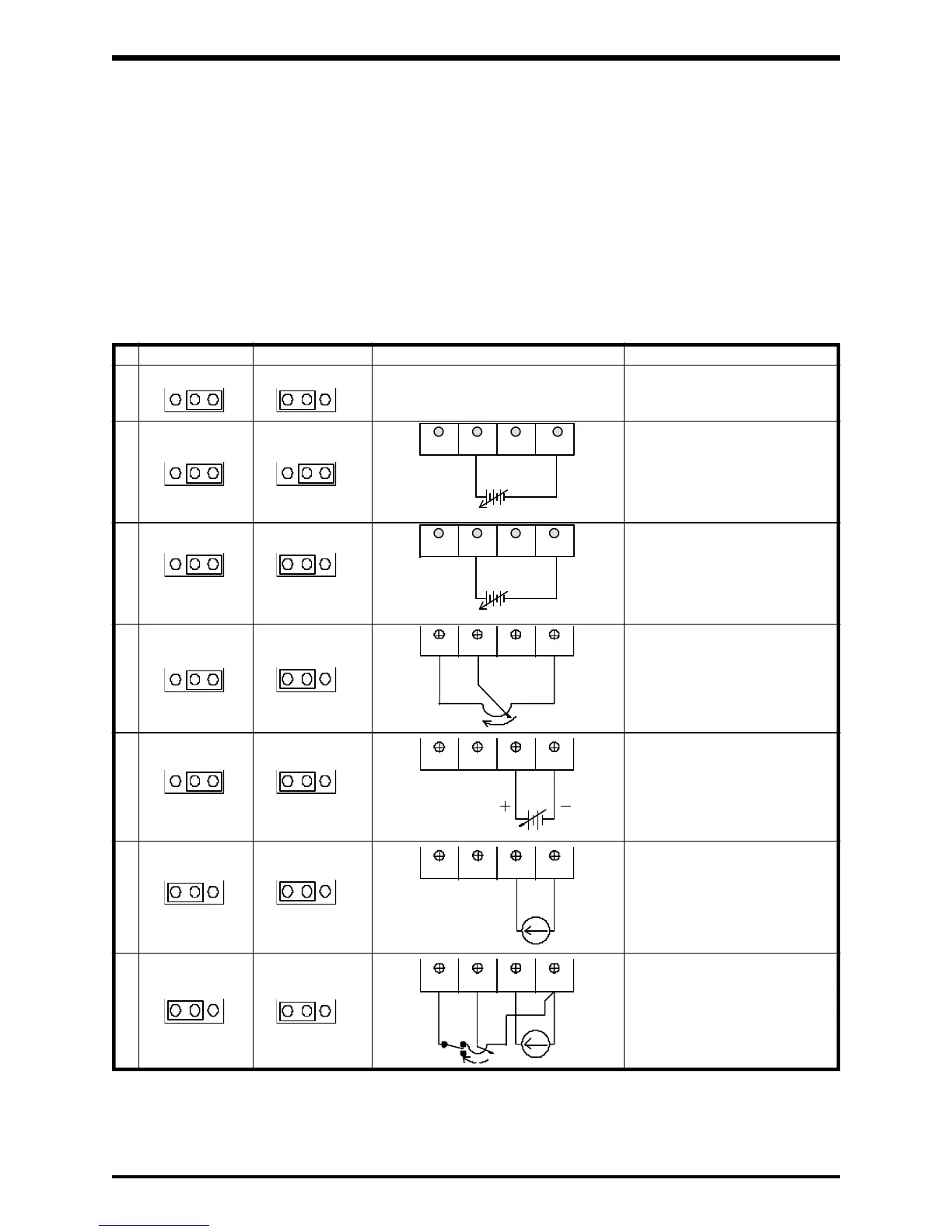
8.4.1 Proportional/Follower Input Signals
The following table illustrates the connections required for receiving the different
analog input signals.
N/A
+
I V 10V 5V
I V
10V 5V
PP
RR IV CC
I V
10V 5V
PP
RR IV CC
0~20mA
(4~20mA)
PP
RR IV CC
PP
RR IV CC
3k ohm
SW
0~20mA
(4~20mA)
0~5Vdc
N/A
N/A
RR IV CCPP
RR IV CCPP
0~10Vdc
0~5Vdc
+
_
_
Terminal/Jumper Connections for Input Reference Signals
Required for standard 0~5Vdc input
reference signal. Function No. 5
RR terminal priority should be set to
1 "on" when using this feature.
See Ref. page 8-23.
Required for standard 0~10Vdc input
reference signal. Function No. 5
RR terminal priority should be set to
1 "on" when using this feature.
See Ref. page 8-23.
3
Required when using a 3k ohm pot.
A 1K to 10K ohm pot can also be
used but the pot adjustments will be
more critical.
4
Required for standard 0~5Vdc input
reference signal. Function No. 5
RR terminal priority should be set to
the normal setting of 0 "off" when
inputting a signal to the IV terminal.
See Ref. page 8-23.
5
6
Required for standard 0~20mA,
4~20mA input reference signal.
Function No. 5 RR terminal priority
should be set to the normal setting
of 0 "off" when inputting a signal to
the IV terminal. See Ref. page 8-23.
6*
JP1 JP2
NO CONNECTIONS, JP1 & JP2 should be
set as shown for normal panel operation.
Required for normal panel operation.
FunctionTerminal Connections
1
When switch is closed (ON), the
remote pot will override the
0~20/4~20mA input reference
signal. Function No. 5 RR terminal
priority should be set to the normal
setting of 0 "off".
10V 5VI V
10V 5VI V
I V
10V 5V
I V 10V 5V
2
 Loading...


