TOSHIBA
Voltage Boost 0 to 30 % 3 8-21
Auto torque boost 0: Off 0 8-21
(voltage) 1: On
Max. voltage frequency 25 to 400 Hz 60 8-21
V/f pattern 0: Constant torque 0 8-21
1: Variable torque
8 - 1
8.0 Operating Procedures
A thorough understanding of the G2+ inverter's operating procedures and functions is necessary
to gain maximum use of the many versatile features. This includes understanding the uses for
all of the available functions, how the software is structured, and the programming techniques
used. An understanding of the use of the input and output terminals is also necessary.
Section 8 identifies operating procedures and teaches keyboard data flow and terminal functions
so the user can program the inverter to fit almost any application.
Section 8 is broken into separate sub-sections that explain the functions of both the keypad
data entry and the terminal input logic. Each function is explained and some step-by-step
procedures are shown with keystroke, action, and display examples.
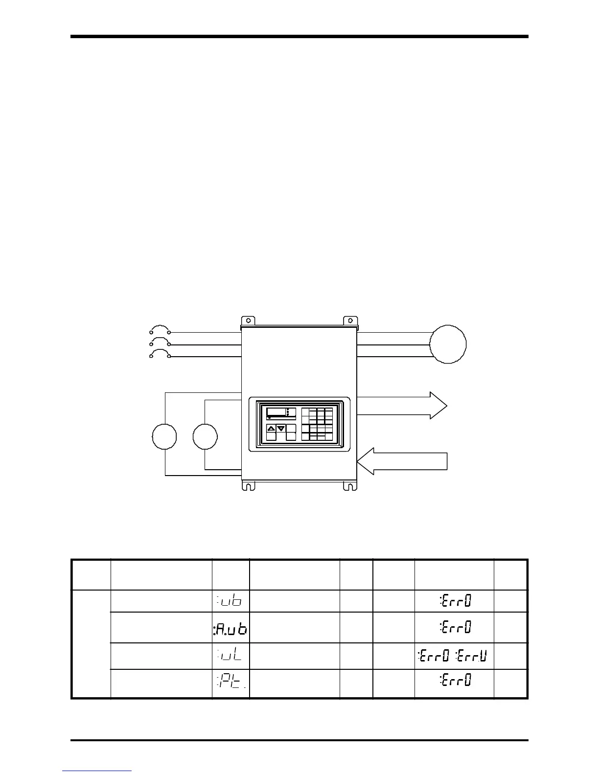
The figure and table shown below, as well as the flowchart and program sequence on the next
page, help to illustrate the basic fundamentals, software structure, and programming format of
the inverter.
1
INPUT SIGNALS (REMOTE CONTROL)
Function Function Adjustment Unit Factory Error Ref.
No. Name Display Range Set Message Page
3-PHASE
POWER
SOURCE
AM FM
REMOTE METERS
INPUT POWER
OUTPUT SIGNALS
OUTPUT POWER
MOTOR
(PANEL CONTROL)
TOSVERT
G2+
Function Parameters
 Loading...


