TOSHIBA
Function Function Adjustment Factory Error Ref.
No. Name Display Range Unit Set Message Page
8 Multifunction output 0: LL, UL
1: LOW, UL 3 8-24
2: LL, RCH
3: LOW, RCH
Low speed detection 0.0 to Max. frequency Hz 0.5 8-28
Speed reach selection 0: Complete ACC/DEC 0 8-28
2ND 1: Frequency reach reference
3
Speed reach detection 2.5 to 25 Hz 2.5 8-28
range
Speed reach reference 0.0 to Max. frequency Hz 0 8-28
8.5 Output Signals
The inverter provides terminals for outputting signals to external components. A number
of selectable "operating" output signals, as well as "fault" output signals, are available.
These output signal terminals are located on the terminal board. The terminals and type
of selections available are shown below.
8.5.1 Selectable Outputs
Function Parameters
8 - 16
ON
ON ON
LOW
Hz
Output
frequency
TIME
TIME
TIME
Across
RCH-P24
Across
LOW-P24
Output signals:
LL
ON
ON
UL
Output
frequency
Hz
TIME
TIME
TIME
Across
LL-P24
Across
UL-P24
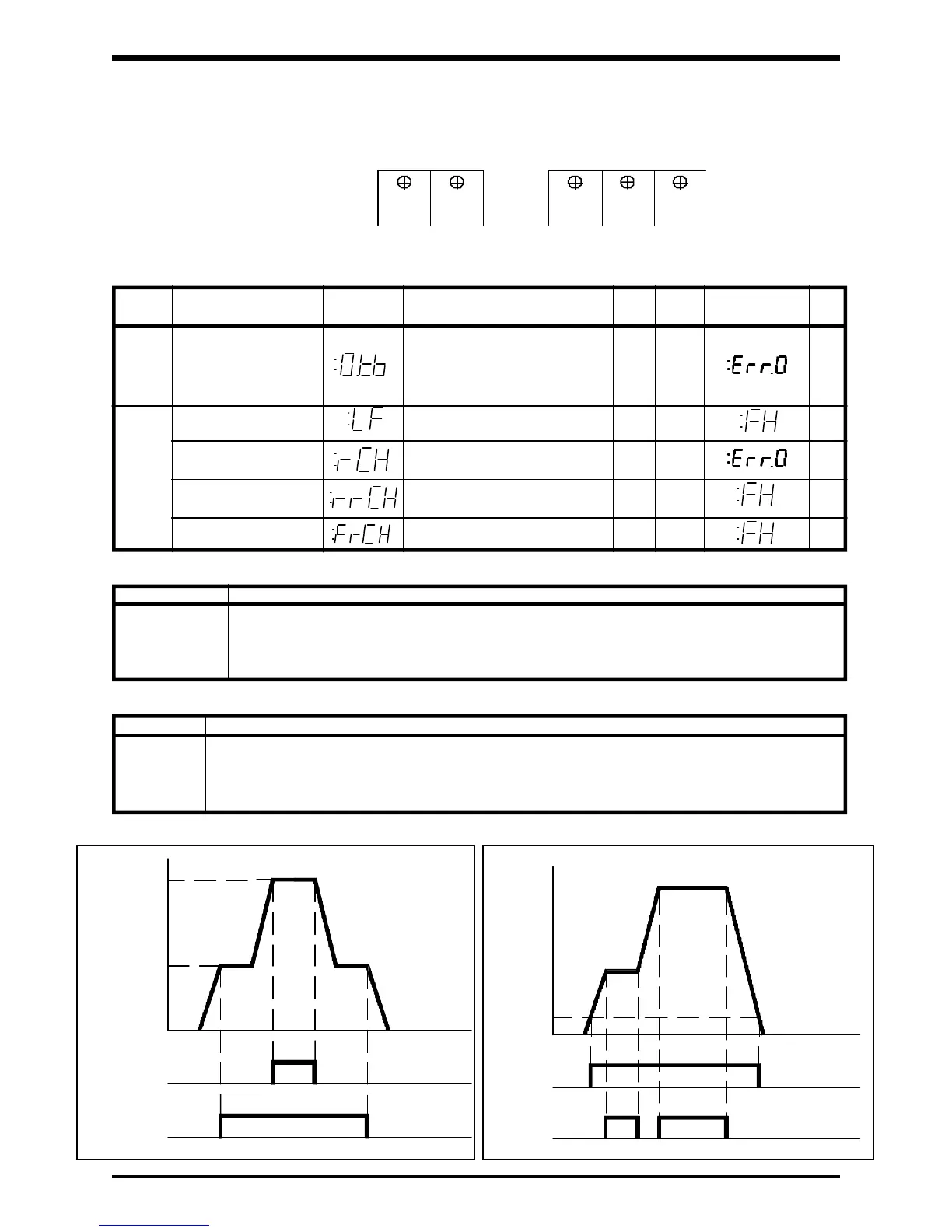
Output signals:
Upper/lower limit frequency signal output Low speed/speed reach signal output with rCH=0
Selectable function output signals (open-collector with 50mAdc~24Vdc ratings)
Setting on 0.tb Function
0 LL, UL (for lower limit and upper limit frequency signal)
1 LOW, UL (for low speed and upper limit frequency signal)
2 LL, RCH (for lower limit frequency and speed reach signals)
3 LOW, RCH (for low speed and speed reach signals)
Terminal Output Signal Selections
Terminal Function
UL
LOW
RCH
LL
Outputs a signal when frequency is = or > the LL value.
Outputs a signal when frequency is = UL value.
Outputs a signal when frequency is = or > the LOW SPEED DETECTION VALUE "LF".
Outputs a signal based upon the selection of the RCH parameters rCH, rrCH, FrCH.
RCH
(UL)
LOW
(LL)
FLA FLB FLC
Output Terminals
 Loading...


