TOSHIBA
6.5 Function Access/Set - Status Keys
Note:
Each key (0-9) has three separate functions: numerical value, first function,
and second function. See Operating Panel (Section 6.1)
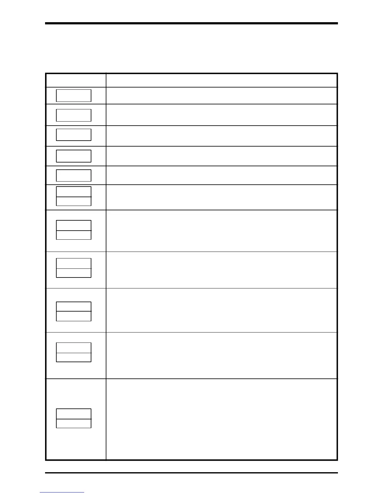
Key Function
Toggles between the monitor and function mode.
Switches to the second function mode.
Used to initiate several functions (ie. JOG, Preset Run, Pattern Run).
Displays the next item within the function. Also cycles through the inverter's
status codes.
Clears the display. Also clears inverter after a trip.
(Must press CLR/WRT to reset inverter after a trip)
Stores each piece of data into the inverters memory (file).
"." is a decimal point.
"READ" displays the inverter's data contents for an individual function.
"0" is the numerical zero.
1st FUNCTION MODE: Selects the standard setting mode. Also sets the
maximum frequency (disabled during a run).
2nd FUNCTION MODE: Sets the start-up frequency and run frequency.
Also sets the run frequency hysteresis.
"1" is the numerical one.
1st FUNCTION MODE: Sets the voltage boost, auto torque boost, maxi-
mum voltage frequency, and V/F pattern.
2nd FUNCTION MODE: Sets the DC injection starting frequency, DC
injection voltage, and DC voltage injection time.
"2" is the numerical two.
1st FUNCTION MODE: Sets the ACC/DEC time for ACC 1, 2 and DEC 1, 2.
Selects the ACC/DEC pattern for 1, 2.
Selects ACC/DEC 1 or 2.
2nd FUNCTION MODE: Sets the multiply factor of display frequency scaler.
"3" is the numerical three.
1st FUNCTION MODE: Sets upper and lower frequency limits.
2nd FUNCTION MODE: Sets low speed detection output.
Selects speed reach selection output option.
Sets speed reach detection range and speed reach
reference frequency.
"4" is the numerical four.
1st FUNCTION MODE: Sets overload detection level (% of rated current),
stall activation level, and also selects the overload
detection curve characteristics.
2nd FUNCTION MODE: Sets the output voltage adjustment (% of input
voltage).
Selects the dynamic braking resistor option and the
OLr option.
Selects the auto deceleration option when no
dynamic braking resistor is used.
6 - 5
.
WRT
UL/LL
3
ACC/DEC
2
V/F
1
FMAX
0
READ
NEXT
2ND
MON
OL
4
CLR
 Loading...


