7-17
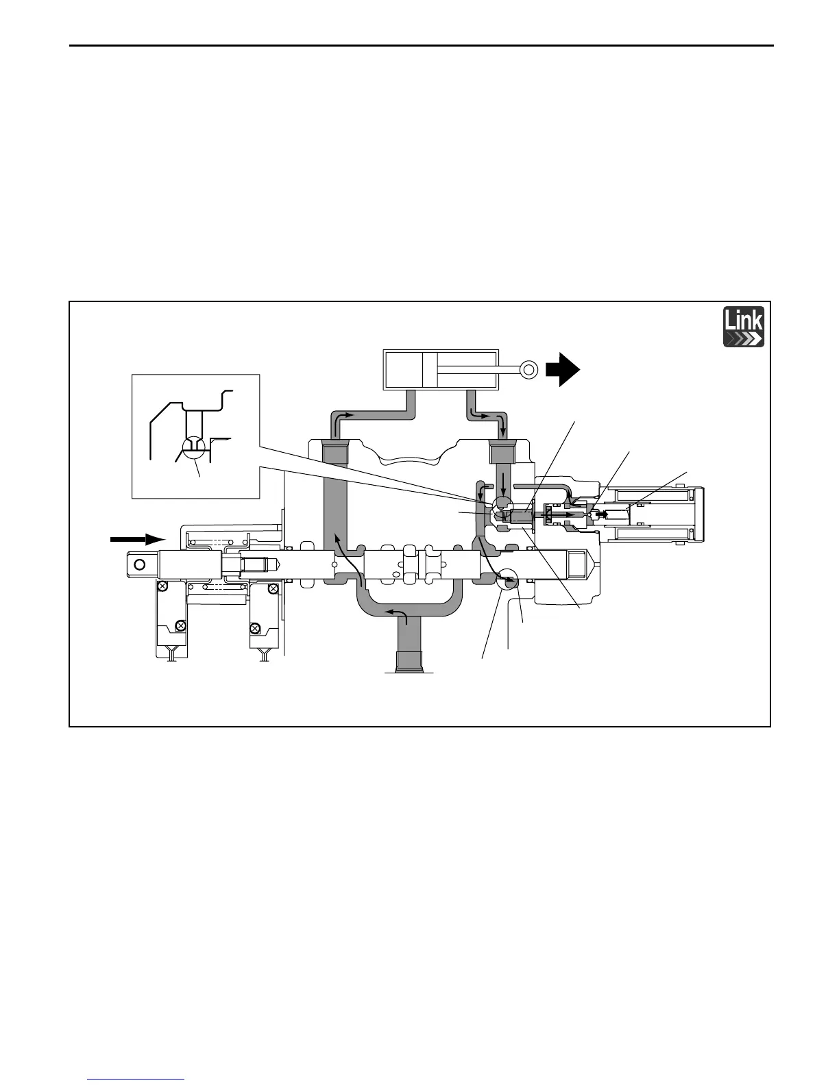
2. Mast forward tilting (solenoid valve: ON)
(1) When the key switch is turned ON and the tilt lever is operated in the forward tilting direction, the tilt
spool is pushed and moves to the right side in the figure.
(2) Then, the circuit connecting the pump port to the C2 port opens. Since the C2 port is connected to
the LH chamber of the tilt cylinder, the pump pressure is applied to the LH chamber of the tilt
cylinder through the C2 port.
(3) Meanwhile, the tilt solenoid valve is turned ON when operated for forward tilting. The poppet in the
solenoid valve moves to the right side in the figure to open the check valve. Then the hydraulic oil in
the RH chamber of the tilt cylinder flows through the C3 port, right side of the logic valve, the
solenoid valve, the left side of the logic valve and the tilt spool to the tank port.
(4) Then, part A of the logic valve forms an orifice. Therefore, the hydraulic oil is led from the right side
of the logic valve to the spool and then to the tank port, and the hydraulic oil at the C3 port flows
gradually to the right side of the logic valve because of restriction by the orifice at logic valve part A.
Tilt cylinder
C2
C3
Tilt spool constriction
Poppet
Logic valve right side
Logic valve right
side
Part A
Orifice
Tilt spool
Pump port
Tilt logic valve
Tank port
Solenoid valve
Check valve
 Loading...