9-18
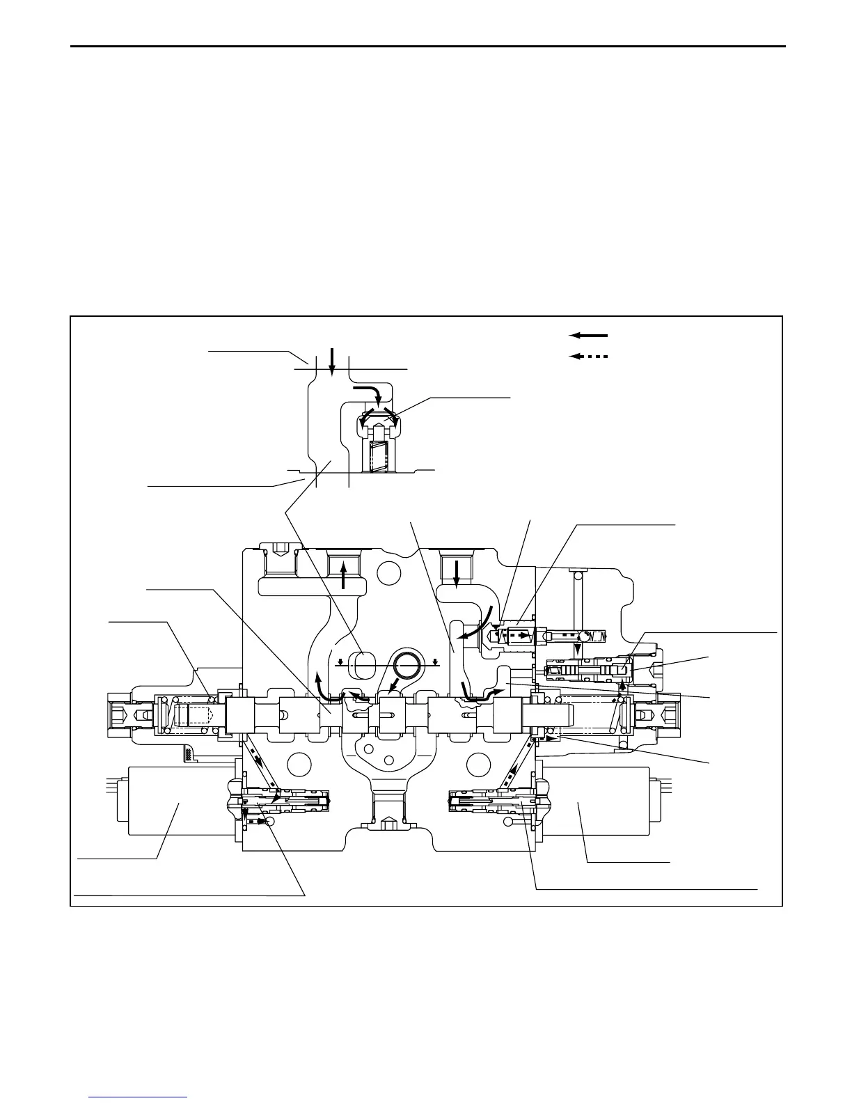
7. FORWARD tilt operation
When the tilt lever is pushed to the FORWARD side, solenoid a2 is energized and the solenoid
proportional valve moves to the left. Then the pressure oil controlled by the pressure reducing valve
flows to chamber (p) on the right side, and the tilt spool moves to the left side.
The volume of oil that flows to chamber (p) is proportional to the distance the lever is operated.
Pressure oil flowing from chamber (a) in the inlet section pushes down the load check, then flows from
port C2 to the bottom of the tilt cylinder.
Pressure oil flowing to chamber (p) enters chamber (n), and shifts the select valve to the left.
The circuit is configured so that oil from the tilt cylinder rod side flows from port C3 through the tilt lock
check valve and chamber (y) to chamber (g).
This generates a pressure differential before and after orifice G, and the shifting of the tilt lock valve to
the right causes the oil on the tilt cylinder rod side to return to the tank.
FORWARD tilt operation (tilt section)
(a)
(y)
TT
G
(n)
(p)
(g)
Main flow/excess flow
Pilot flow
Tilt section
Load check
Attachment section
Section T-T
Port C2 Port C3
Tilt spool
Solenoid b2
Electromagnetic proportional valve
Spring 7
Electromagnetic proportional valve
Solenoid a2
Logic selection valve
Lift logic valve
 Loading...