9-21
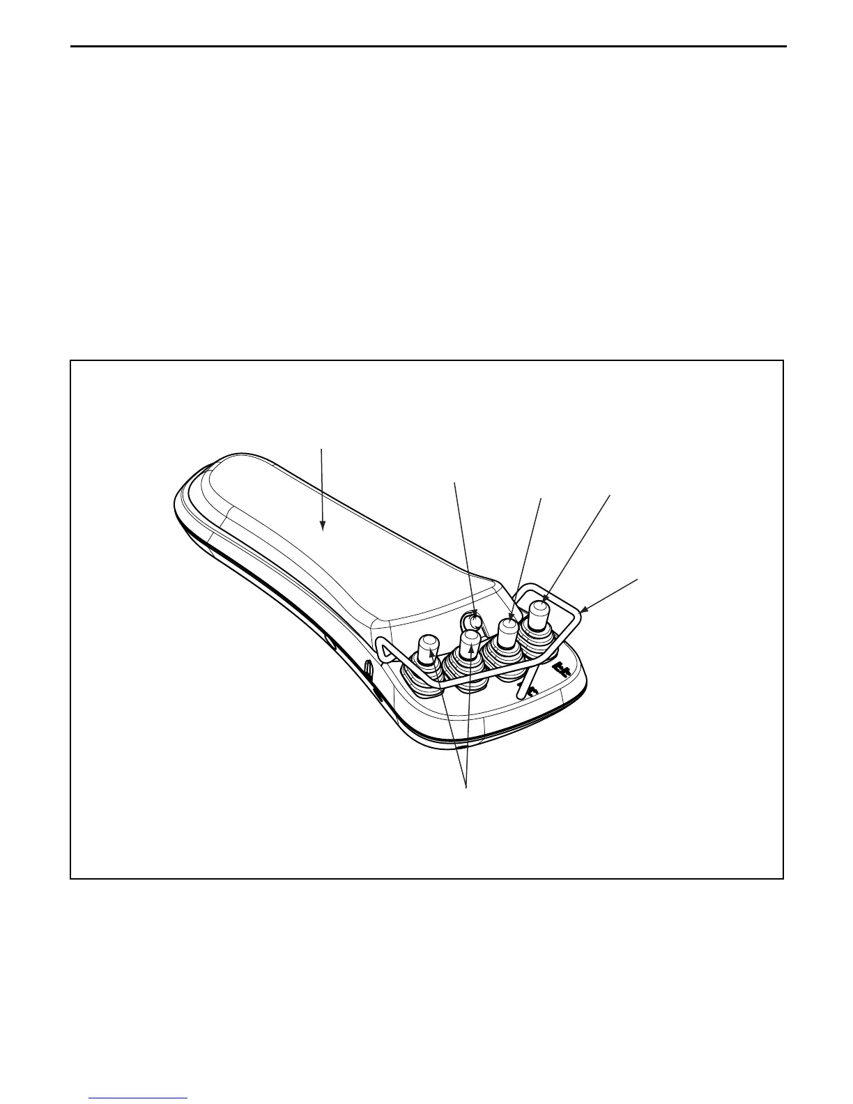
■ Mini Lever Structure
Mini levers strongly desired in the US market are provided as options.
• The material handling levers positioned above the instrument panel on previous models are installed on
the right front side of the seat and the lever stroke and operating force are decreased for easier
operation with less fatigue.
• Since they are single-axis levers independent for the forward and backward directions like the manual
levers on previous models, previous model operators can easily handle new models.
• The automatic fork leveling switch is installed behind the tilt lever. When the button is pressed once, the
operated state is stored mechanically by the lock mechanism in the switch for automatic leveling of the
fork at the time of stopping. Pressing it again releases locking to return to the original state without
automatic leveling. (See the mast control section for further details of the function.)
• The lever box position can be adjusted in the longitudinal direction. Loosen the lever box fixing knob, set
the box in the position desired by the operator, and tighten the knob for fixing.
• Levers are guarded all around.
• Material handling operation is disabled while the operator leaves the seat.
Arm pad
Tilt lever
Lift lever
Guard
Fork automatic
leveling switch
Att lever
 Loading...