9-19
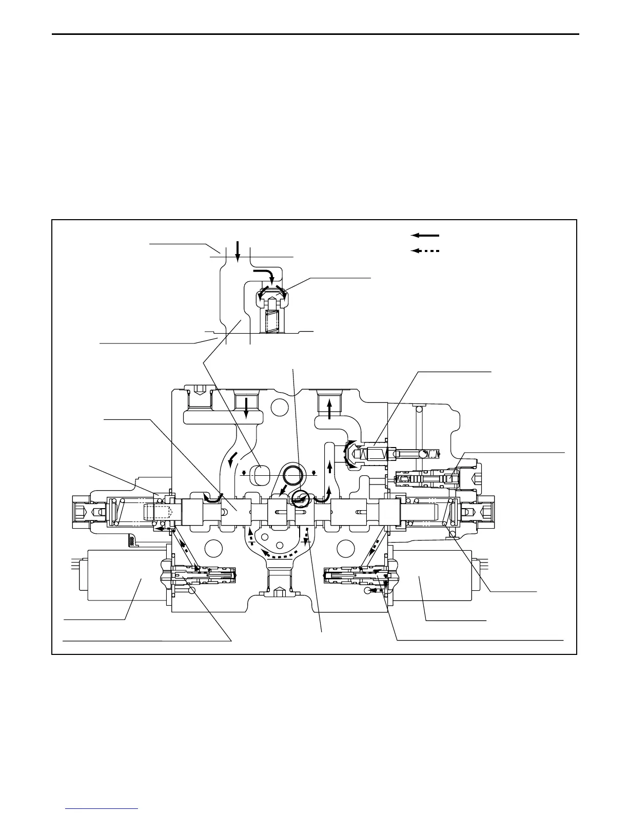
8. REAR tilt operation
When the tilt lever is pushed to the REAR side, solenoid b2 is energized and the solenoid proportional
valve moves to the right. Then the pressure oil controlled by the pressure reducing valve flows to
chamber (w) on the left side, and the tilt spool moves to the right side.
The volume of oil that flows to chamber (w) is proportional to the distance the lever is operated.
Pressure oil flowing from chamber (a) in the inlet section pushes down the load check and shifts the tilt
lock check valve, then flows from port C3 to the tilt cylinder rod side.
The select valve does not operate at this time, so the select valve becomes simply a check valve.
The pressure differential between chamber (a) and chamber 7 is kept constant by the pressure
compensation mechanism and the load sensing mechanism, so the volume of pressure oil supplied to
port C3 is determined by the opening aperture of part O irrespective of the load.
REAR tilt operation (tilt section)
7
(a)
UU
(w)
O
Main flow/excess flow
Pilot flow
Load check
Tilt section
Attachment section
Section U-U
Port C2 Port C3
Lift logic valve
Logic selection valve
Tilt spool
Solenoid b2
Electromagnetic proportional valve
Electromagnetic proportional valve
Solenoid a2
Spring 8
 Loading...