2-8
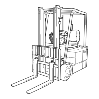
7. The rotational magnetic field is as explained below.
(1) Assume that three coils are placed on the outer side the rotor. When these three coils (a1-a2, b1-b2
and c1-c2) are connected and a three phase alternate current flows, the magnetic flux varies as
shown in the figure below to generate a 2-pole rotational magnetic field. The rotating magnetic field
makes one turn in one cycle of the three-phase AC. Since the field rotates once in one cycle of the
three-phase AC, the inner rotor also makes one turn.
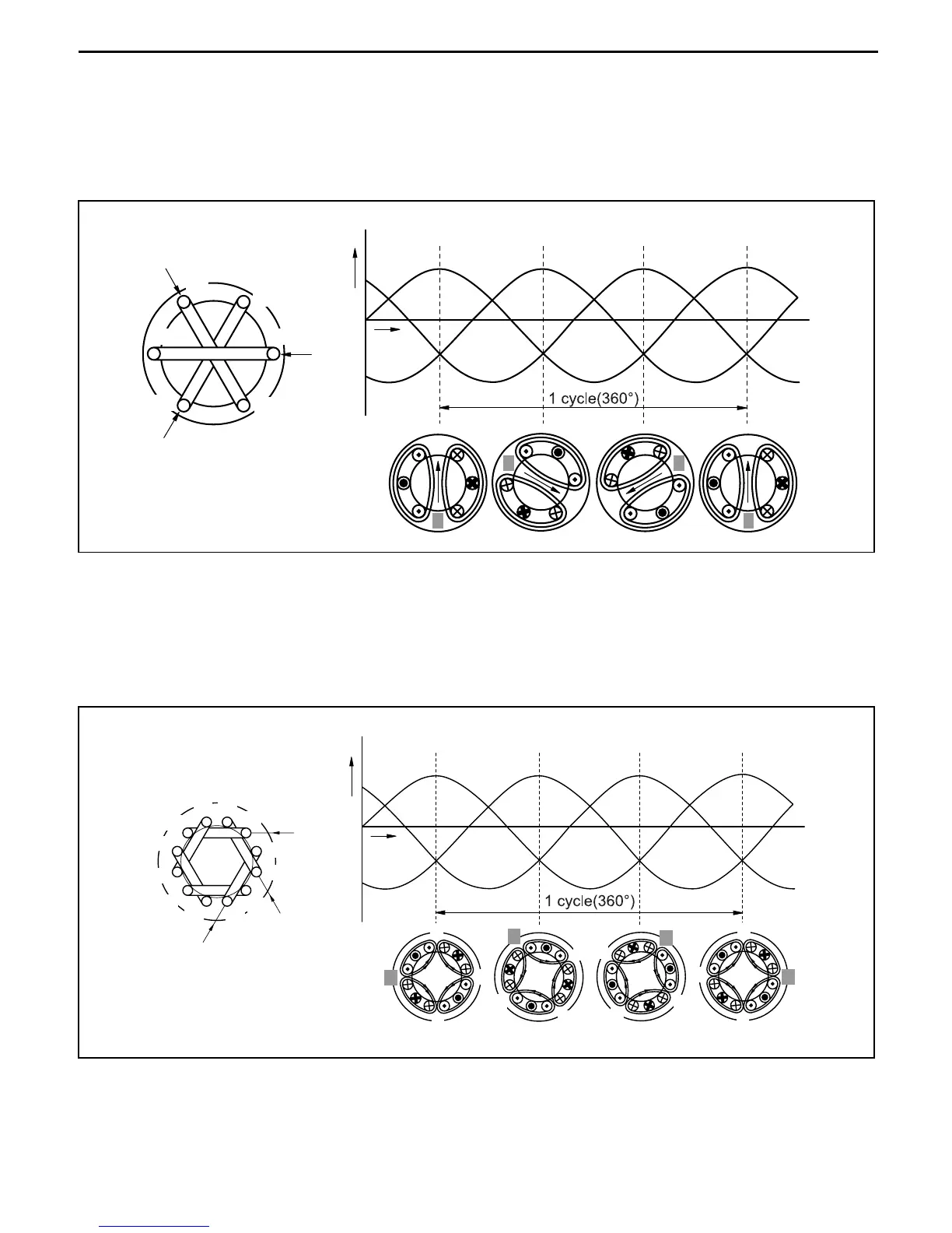
(2) See the internal structure of the motor. Six coils in three pairs are placed on the outer side of the
rotor. When the six coils (a1a1' - a2a2', b1b1'-b2-b2' and c1c1'-c2c2') are connected in three
phases to receive a three-phase alternate current, the magnetic flux varies as shown in the figure
below to generate a four-pole rotational magnetic field. In this case, the rotational magnetic field
makes a 1/2 turn in one cycle of the three-phase AC. In a motor with three phases of magnetic field
(using six coils in three pairs), the inner rotor can generate twice as much torque as was in the case
of a single-phase motor (using three coils).
ia
a2
b1
a1
c2
b2
c1
ic
ib
Current (i)
t1
ia ib ic
t2 t3 t4
Time (t)
S
SS
S
N
N
N
N
a1’
c2 b1’
a1
c1’
a2’
c1
b2’
a2
c2’
b2
b1
ib
ic
ia
t1 t2 t3 t4
ia ib ic
S
N
S
S
S
S
S
S
S
N
N
N
N
N
N
N
Current (i)
Time (t)
 Loading...