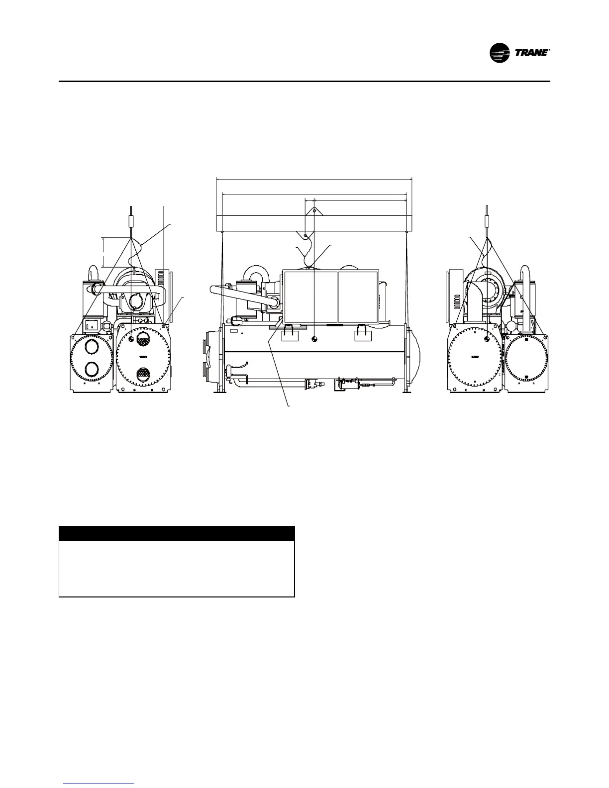
1. LIFTING CABLES (CHAINS) WILL NOT BE THE SAME LENGTH.
ADJUST TO KEEP UNIT LEVEL WHILE LIFTING.
2. ATTACH ANTI-ROLLING CABLE (CHAIN) AS SHOWN WITHOUT TENSION.
NOT AS A LIFTING CABLE, BUT TO PREVENT UNIT FROM ROLLING.
3. DO NOT FORK LIFT UNIT.
4. WEIGHTS ARE TYPICAL FOR UNITS WITH R-134a CHARGE.
5. IF UNIT IS DISASSEMBLED, SEE SERVICE BULLETIN
FOR LIFTING AND RIGGING OF COMPONENTS.
WARNING: DO NOT USE CABLES (CHAINS) OR SLINGS EXCEPT AS SHOWN.
OTHER LIFTING ARRANGEMENTS MAY CAUSE EQUIPMENT DAMAGE OR
SERIOUS PERSONAL INJURY.
4. Attach cables to lifting beam. Total lifting weight, lift-
ing weight distribution and required lifting beam di-
mensions are shown in the rigging diagram shipped
with each unit and in Figure 10. The lifting beam
crossbar must be positioned so the lifting cables do
not contact unit piping or electrical panel enclosure.
D
WARNING
Anti- rotation Strap!
Connect an anti-rotation strap between the lifting
beam and compressor before lifting unit. Failure to do
so may result in death or serious injury should a lifting
cable fail.
5. Connect an anti-rotation strap or cable loosely be-
tween the lifting beam and the threaded coupling or
eyelet provided at the top of the compressor. Use an
eyebolt or clevis to secure the strap at the coupling
or eyelet.
Note: The anti-rotation strap is not a lifting chain, but
a safety device to ensure that the unit cannot tilt
during lifting.
Alternate Moving Method
6. If it is not possible to rig from above as shown in the
figures, the unit may also be moved by jacking each
end high enough to move an equipment dolly under
each tube sheet support. Once securely mounted on
the dollies, the unit may be rolled into position.
Isolation Pads
The elastomeric pads shipped (as standard) are adequate
for most installations. For additional details on isolation
practices, refer to Trane Engineering Bulletin -Series R®
Chiller Sound Ratings and Installation Guide., or consult
an acoustical engineer for sound-sensitive installations.
7. During final positioning of the unit, place the isola-
tion pads under the evaporator and condenser tube
sheet supports. Level the unit.
 Loading...


