Installation Mechanical
34 RTHD-SVX02H-EN
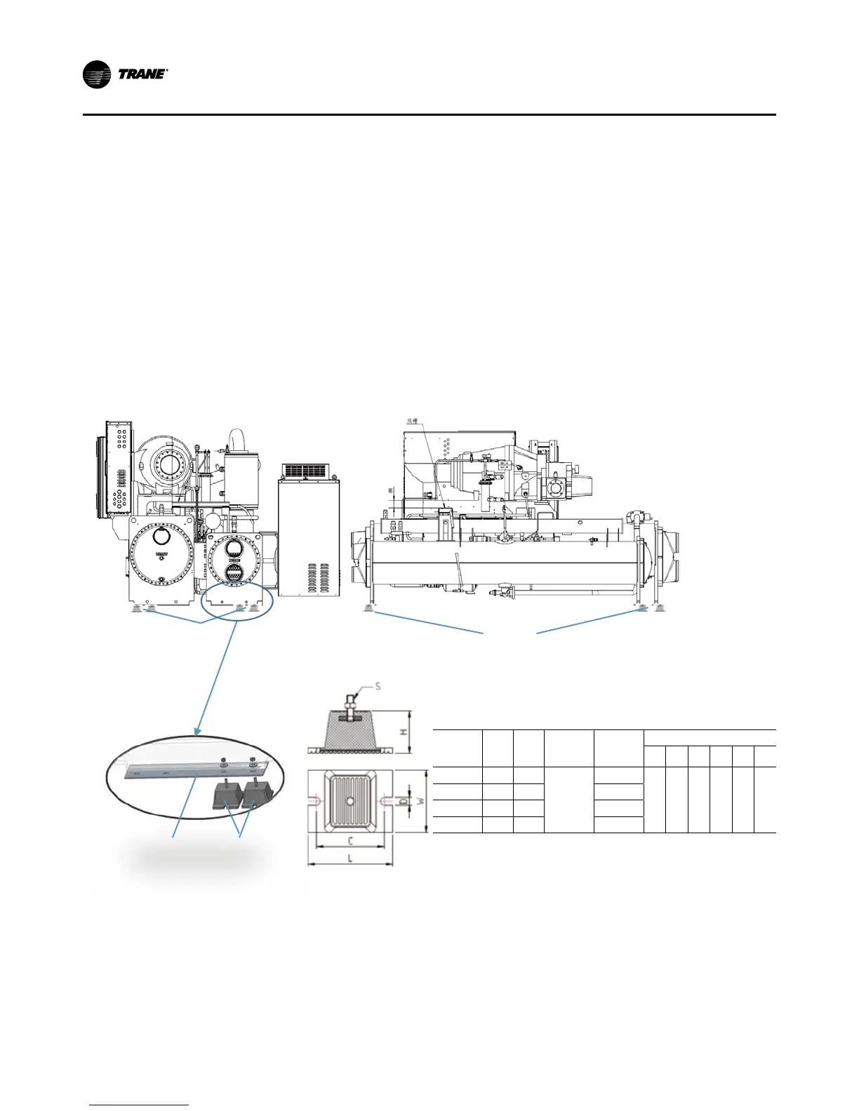
Figure 11. Isolator Pad Placement
Technical data of rubber AVM
Model
Load
(kg)
Load
(Lbs)
Deection
(±3mm)
Vertical
Rigidity
(kg/mm)
Outer Size(±2mm)
L W H C ØD S
HA-700 700 1543
12
58.33
159 118 70 127 14 M12
HA-1000 1000 2205 83.33
HA-1400 1400 3086 116.67
HA-1800 1800 3968 150.00
Bottom plate
Isolator
Isolator
Isolator
9. The unit is shipped with four spacers (only three on
B family) on the compressor mount that protect the
compressor isolation pads during shipping and in
handling. Remove these spacers (Figure 12) before
the unit is operated.
10. Remove the shipping brackets from the bottom sides
of the oil separator(s) (see Figure 12).
Note: Once shipping bracket(s) is removed, the oil sep-
arator is only supported by the discharge line.
Placement Neoprene Isolator Installation
(optional)
8. Install the optional neoprene isolators at each mount-
ing location.
8.1. Secure the isolators to the mounting surface,
using the mounting slots in the isolator base
plate, as shown as below. Do not fully tighten
the isolator mounting bolts at this time.
8.2. Align the mounting holes in the base of the unit,
with the threaded positioning pins on the top of
the isolators.
8.3. Lower the unit on to the isolators and secure the
isolator to the unit with a nut. Maximum isolator
deflection should be approximately 1/4”.
8.4. Level the unit carefully. Refer to “Leveling”. Fully
tighten the isolator mounting bolts.
8.5. Two Isolators for each foot, refer to Figure 11 ,
total 8 isolators installed for one chiller.
 Loading...


