Oil Filter
Optional Oil
Cooler
Oil Heaters
Master Oil Line
Solenoid
Oil Separators
Oil Sump
Vent to
Condenser
To Bearings
Injection to
Rotors
Oil Return
Gas Pump
Vent Line
To Condenser
Pressure
Oil/Refrigerant
Mixture
Oil Recovery
Fill Solenoid
Valve
Drain Solenoid
Valve
Liquid/Vapor
Refrigerant Mixture
Condenser
EXV
Primary Oil System
Refrigerant & Oil
Mixture-Oil Recovery
System
Manual
Service
Valve
Optical Oil
Detector
Oil Pressure
Transducer
Condenser
Pressure
Transducer
Other
Oil Return Filter
restrictor
Compressor
Compressor
Discharge
Temperature
Sensor
Manual
Service
Valve
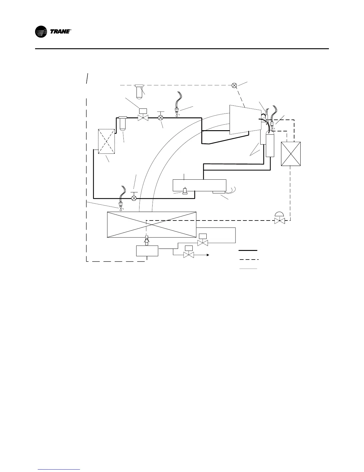
Oil Flow Protection
Oil flowing through the lubrication circuit flows from the
oil sump to the compressor (see Figure 39). As the oil
leaves the sump, it passes through a service valve, an oil
cooler (if used), oil filter, master solenoid valve, and an-
other service valve. Oil flow then splits into two distinct
paths, each performing a separate function: (1) bearing
lubrication and cooling, and (2) compressor oil injection.
Oil flow and quality is proven through a combination of
a number of sensors, most notably a pressure transduc-
er and the optical oil level sensor.
If for any reason oil flow is obstructed because of a
plugged oil filter, closed service valve, faulty master so-
lenoid, or other source, the oil pressure transducer will
read an excessively high pressure drop in the oil system
(relative to the total system pressure) and shut down the
chiller.
Likewise, the optical oil level sensor can detect the lack
of oil in the primary oil system (which could result from
improper oil charging after servicing, or oil logging in
other parts of the system). The sensor will prevent the
compressor from starting or running unless an adequate
volume of oil is present. The combination of these two
devices, as well as diagnostics associated with extended
low system differential pressure and low superheat con-
ditions, can protect the compressor from damage due
to severe conditions, component failures, or improper
operation.
If the compressor stops for any reason, the master sole-
noid valve closes; this isolates the oil charge in the sump
during “off” periods. With the oil efficiently contained in
the sump, oil is immediately available to the compres-
sor at startup. Such flows would otherwise purge oil
from the lines and the oil sump, which is an undesirable
effect.
To ensure the required system differential pressure is
adequate to move oil to the compressor, the UC800
attempts to both control a minimum system differential
pressure as well as monitor it. Based on readings from
pressure transducers in both the evaporator and con-
denser , the EXV is modulated to maintain evaporator
pressure at a minimum of 25 psid below the condenser
pressure. Once the minimum is met, the EXV will return
to normal liquid level control (see the paragraph on “Cy-
cle Description”. If the differential is significantly lower
than required, the unit will trip and initiate a appropri-
 Loading...


