80 RTHD-SVX02H-EN
Operator Interface Controls
UC800 Overview
Power Supply
The UC800 (1A22) receives 24 Vac (210 mA) power from
the 1A2 power supply located in the chiller control panel.
Wiring and Port Descriptions
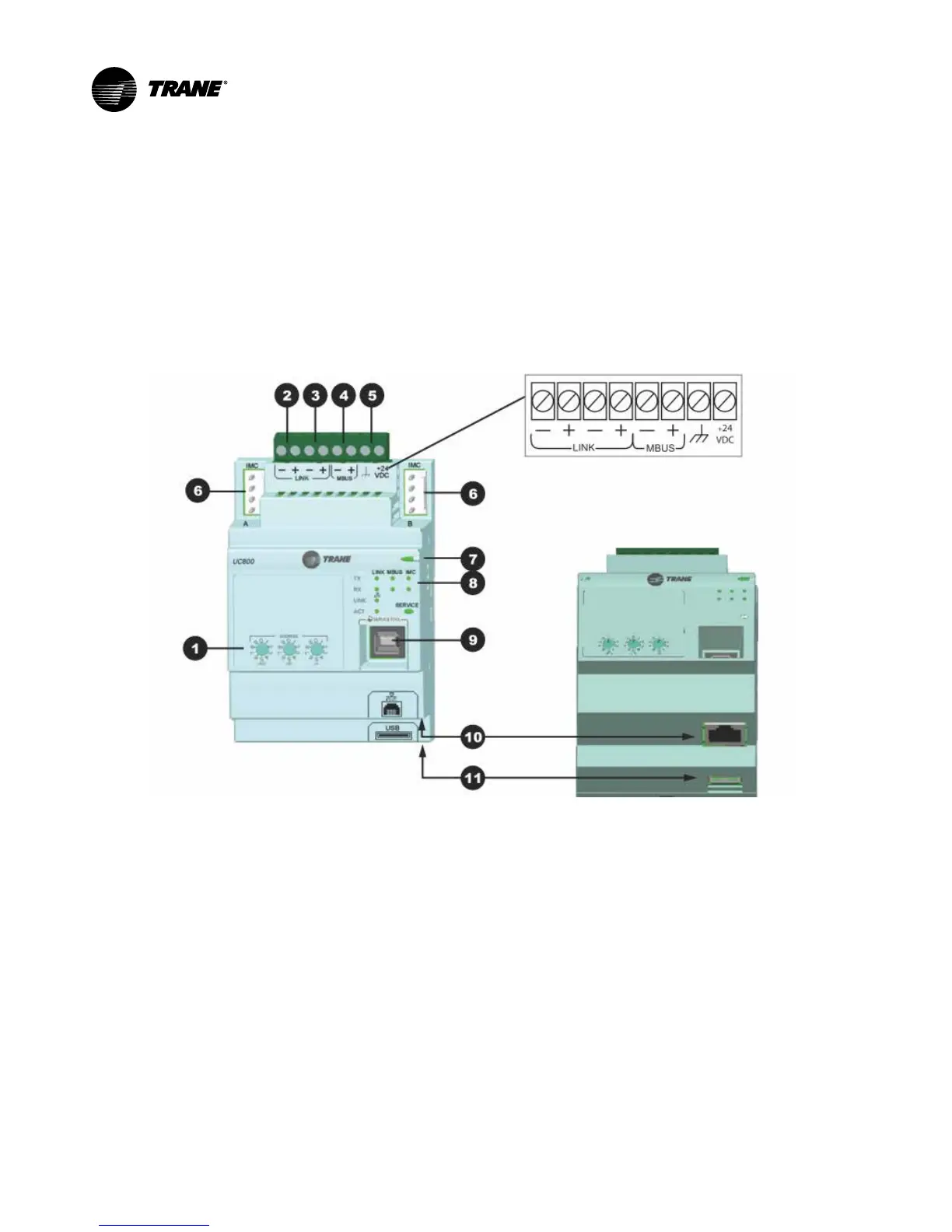
Figure 40 illustrates the UC800 controller ports, LEDs,
rotary switches, and wiring terminals.The numbered list
following Figure 40 corresponds to the numbered call-
outs in the illustration.
Figure 40. Wiring locations and connection ports
Front view
Bottom View
1. Rotary Switches for setting BACnet®MAC address or
MODBUS ID.
2. LINK for BACnet MS/TP, or MODBUS Slave (two ter-
minals, ±). Field wired if used.
3. LINK for BACnet MS/TP, or MODBUS Slave (two ter-
minals, ±). Field wired if used.
4. Machine bus for existing machine LLIDs (IPC3Tracer
bus 19.200 baud). IPC3 Bus: used for Comm4 us-
ingTCI or LonTalk®using LCI-C.
5. Power (210 mA at 24 Vdc) and ground terminations
(same bus as item 4). Factory wired.
6. Not used.
7. Marquee LED power and UC800 Status indicator (Ta-
ble 22).
8. Status LEDs for the BAS link, MBus link, and IMC
link.
9. USB device type B connection for the service tool
(Tracer TU).
10. The Ethernet connection can only be used with theT-
racerAdaptiView display.
11. USB Host (not used).