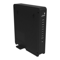
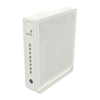
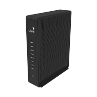
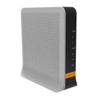
Ubee Interactive Device Panels, Connections and LEDs
Ubee UBC1301-AA00 Advanced Wireless Voice Gateway Subscriber User Guide • March 2017 6
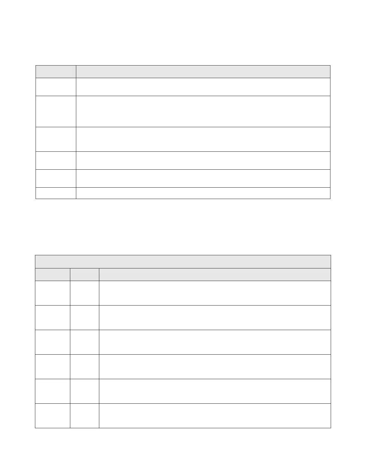
1.5.2 Device Connections
The following table describes the connections on the rear panel of the UBC1301-AA00.
1.5.3 LED Behavior
The following tables summarize the behavior of the LEDs on both the front and rear
panels of the UBC1301-AA00.
Item Description
USB
Use to connect to USB enabled devices such as hard disk drives, and can be used for firmware
upgrade.
RESET
To r es e t t he dev i c e , use a p oin t e d obj e c t l ike the e n d o f a pa p er clip to push down the reset button. To
power cycle the device, hold for less than 5 seconds. To reset to factory default settings, hold for more
than 20 seconds. The UBC1301-AA00 will reset and reboot. Warning: Resetting to factory defaults
will erase any and all settings you have configured and will restore to factory default settings.
ETHERNET
1 - 4
Connects to Ethernet devices such as computers, gaming consoles, and/or routers/hubs using an
RJ45 cable. Each ETHERNET port on the back panel of the device has an LED to indicate its status
when an Ethernet device is connected.
CABLE
Connects to the cable outlet (with the cable provided by your service provider), or a cable splitter
connected to the cable outlet.
TEL 1
TEL 2
Connects to standard telephones using an RJ11 cable. Telephone service must be enabled by your
service provider.
POWER Connects the power cable to the device. Use only the power cable provided with the UBC1301-AA00.
FRONT PANEL
LED Color Description
POWER Green
On – Internal power-on completed successfully.
Flashes – Power-on failed. Note that the LED blinks briefly immediately after powering on
the device.
DS/US
(downstream/
upstream)
Green
Flashes – When DS and US scan is in progress.
On – Locked to DS and US channels and registered OK, and when data is being passed.
Flashes – When a firmware upgrade is in progress.
ONLINE Green
Flashes – Obtaining an IP address and configuration file.
On – Configuration completed successfully, network connected.
Off – Network connect failed.
2.4G Green
Flashes – 2.4GHz Wi-F- traffic is being passed.
On – 2.4GHz Wi-F- is enabled.
Off – 2.4GHz Wi-F- is disabled.
5G Green
Flashes – 5GHz Wi-F- traffic is being passed.
On – 5GHz Wi-F- is enabled.
Off – 5GHz Wi-F- is disabled.
TEL1 Green
On – Telephony is enabled.
Off – Telephony is not provisioned.
Flashes– Call is in progress or EMTA is attempting to register.
 Loading...