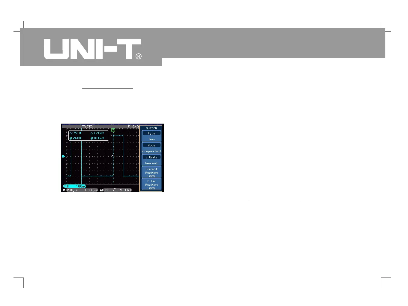
8. Use the control knob to set
cursor 1 at the first falling edge of the pulse
This value is the negative duty ratio.
Measure the phase difference that occurs when a sine
signal passes through the circuit. Connect CH1 to the
input signal of the circuit and connect CH2 to the
output signal of the circuit. To make testing easier,
CH1 and CH2 displacements are set in the centre
point, as shown in Figure 3-8. Follow the steps below :
1. Press [ ] to display t he cu rsor
2. Press [ ] to activate the cursor measurement
3. Press [ ] again to set cursor type to time
ress [ ] to set the vertical cursor unit to Degree
5. Turn the control knob to set
cursor 1 at the center point of the first sine
rising edge where is crosses with channel
III. Measuring the phase difference between two
Figure 3-7 Using the cursors to test pulse
 Loading...