User Manual
Your Trustworthy Industrial IoT Partner www.pusr.com
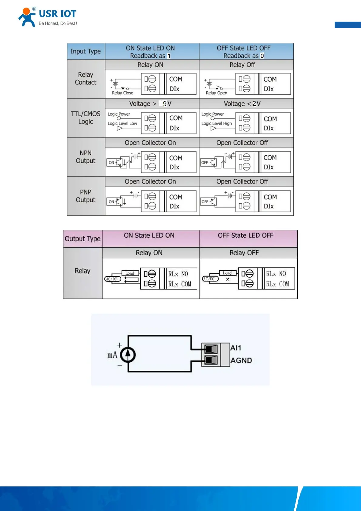
Fig. 3 Dry/Wet contact wiring
Fig. 4 DI wire connection
Fig. 5 DO wire connection
Fig. 6 AI wire connection
NOTE:
–All DI channels should be configured to dry contact or wet contact in the same time
–wire range:28~16 AWG(0.2~0.1 mm
2
), strip length 10mm
2.3.3. Modbus address mapping table
The internal register map of USR-M100 field controller node is the data map of digital input and output and analog input module.
 Loading...