EasyManuals Logo
Home>USR IOT>Gateway>USR-M100

USR IOT USR-M100 User Manual

USR IOT USR-M100
126 pages
To Next Page IconTo Next Page
To Previous Page IconTo Previous Page
Page #12 background imageLoading...
Page #12 background image
User Manual
Your Trustworthy Industrial IoT Partner www.pusr.com
11
Table 3 IO modbus address
Data points
Slave ID
Start address
Register
address
Function
code
Attribute
Data type
Default status
DO 1
100
0000
00001
0x1,0x5,0xF
Write/read
Uint8
NC
DO 2
100
0001
00002
0x1,0x5,0xF
Write/read
Uint8
NC
DI 1
100
0000
10001
0x2
read
Uint8
0
DI 2
100
0001
10002
0x2
read
Uint8
0
AI 1
100
0000
30001
0x4
read
float32(ABCD)
0
AI 2
100
0001
30003
0x4
read
float32(ABCD)
0
2.4. Power supply
The USR-M100 I/O gateway provides 2-pin power supply input terminal. The power supply support anti-reverse protection. Power
supply range: 9~36VDC.
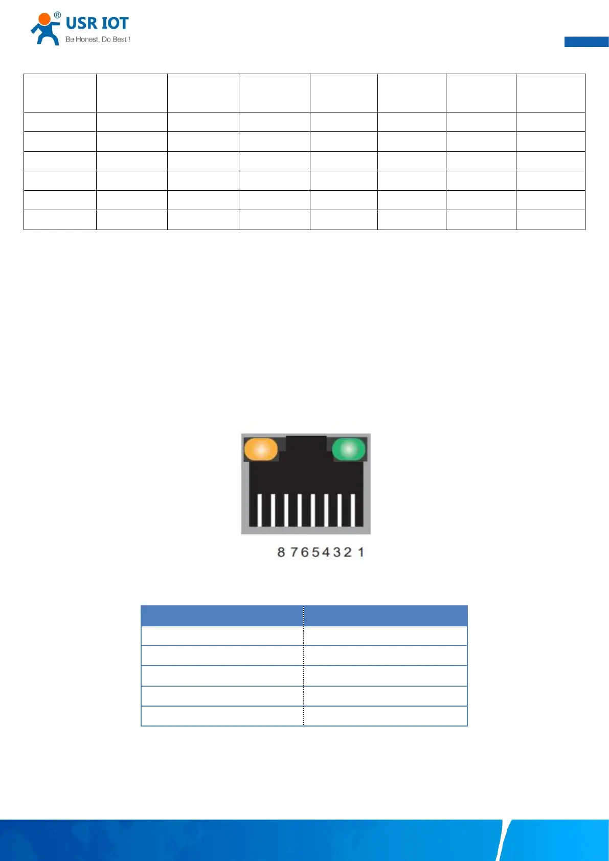
2.5. Ethernet RJ45 interface
The 10Base-T/100Base-TX adaptive Ethernet RJ45 interface supports automatic MDI/MDIX connection, refer to Fig.7 below for the pin
distribution of the RJ45 interface.
Link LED: green color. Lights(steady on) when the module is connected to a network.
Activity LED: orange color. Blinks when network data is transmitted through the port.
Fig. 7 RJ45 with light
Table 4 Ethernet pin assignments
Pin number
Signal name
1
Send data+(TD+)
2
Send data-(TD-)
3
Receive data+(RD+)
6
Receive data-(RD-)
4,5,7,8
Unused
2.6. LED indicators
The USR-M100 smart RTU provides LED indicators to monitor the device working status with a comprehensive simplified
troubleshooting, the LED indicator behaviors are defined below.

Table of Contents

Questions and Answers:

Question and Answer IconNeed help?

Do you have a question about the USR IOT USR-M100 and is the answer not in the manual?

USR IOT USR-M100 Specifications

General IconGeneral
BrandUSR IOT
ModelUSR-M100
CategoryGateway
LanguageEnglish