User Manual
Your Trustworthy Industrial IoT Partner www.pusr.com
Table 23 Data types
Integer 16 bit. Big-endian.high byte first
Unsigned integer 16 bit. Big-endian.
Integer 32 bit. Big-endian.
Integer 32 bit. Little-Endian byte swap
Unsigned integer 32 bit. Big-endian.
Unsigned integer 32 bit. Little-Endian byte swap.
Float 32 bit. Big-endian.
Float 32 bit. Little-Endian byte swap.
Note that these could be referred to in different ways. for example a 4 Byte Signed Integer might be referred to as a 32 bit Integer in
equipment documentation. For binary values we also need to know what “bit” of the register to look at for the binary value. For this
reason a single 16 bit modbus register could represent up to 16 individual binary data points. Sometimes the Data Type is inferred by
listing the number of registers. For example 2 registers might mean a 4 byte value.
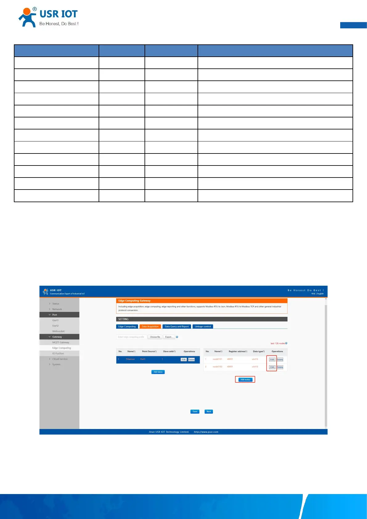
9.2.3. Data points configuration
First select the slave device, click add nodes to add a data point, click edit to configure the data point, click delete to delete a data
point.
Fig. 129 Add modbus data point
 Loading...