User Manual
Your Trustworthy Industrial IoT Partner www.pusr.com
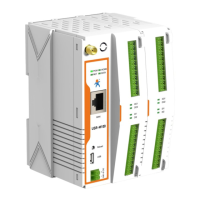
Fig. 130 Data point configuration
In the data point property, enter the node name, select modbus function code, enter the register address and response timeout,
select the right data type, input the calculation formula, the description of the configuration parameters on this interface is shown in
table 15. We use the temperature and humidity data points as an example to describe the process. After finishing configuring the data
points, please scroll down to the bottom of the page and click on "Save" button to save all the changes that you have made. All
configurations take effect after a system reboot.
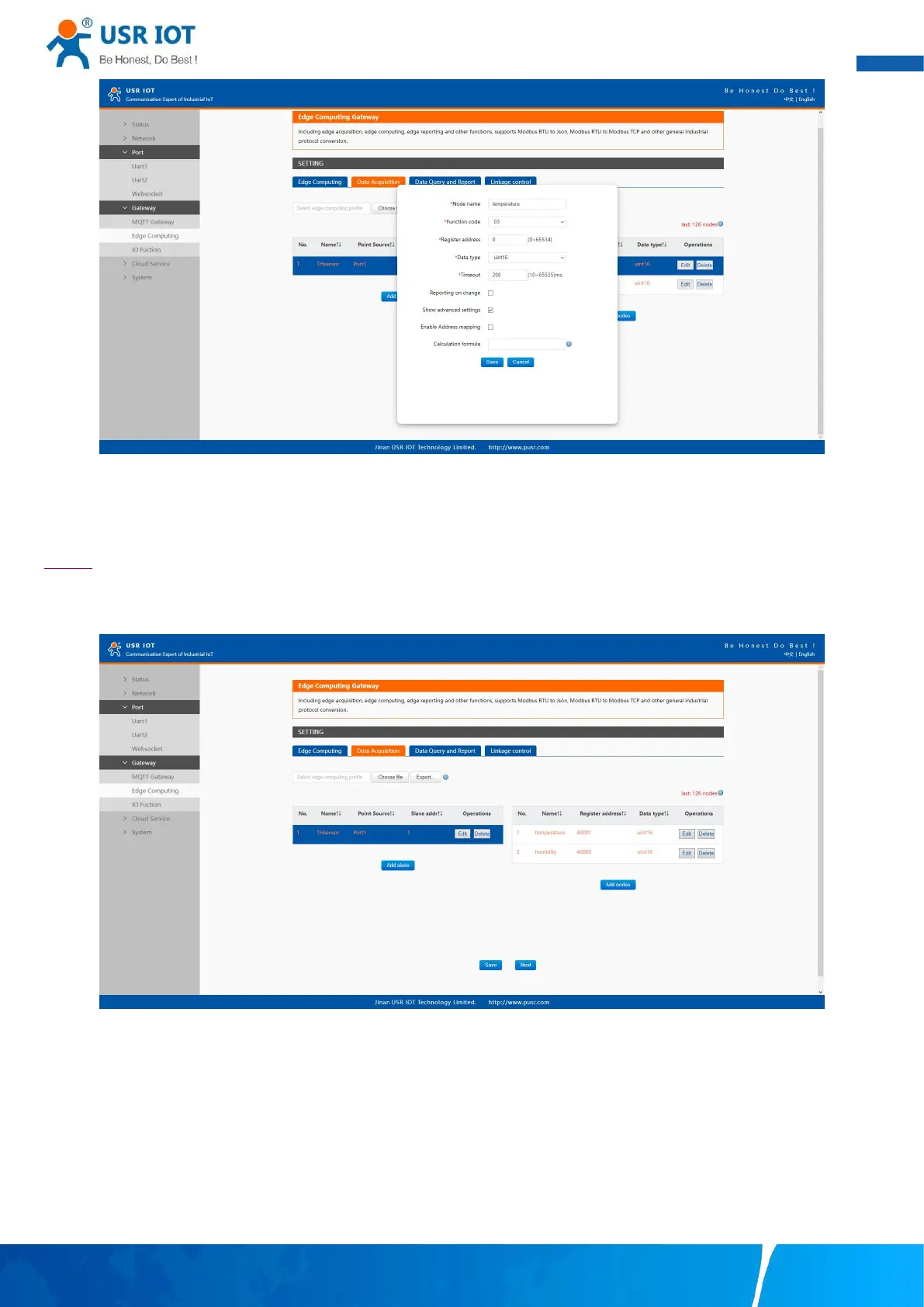
Fig. 131 Sensor register reading
After the correct slave and data points configuration, the modbus polling command will print on the corresponding serial port
regularly, as shown in Fig.132.
 Loading...