22
VERSION 06/2018
ORDER NUMBER DOC 2343275
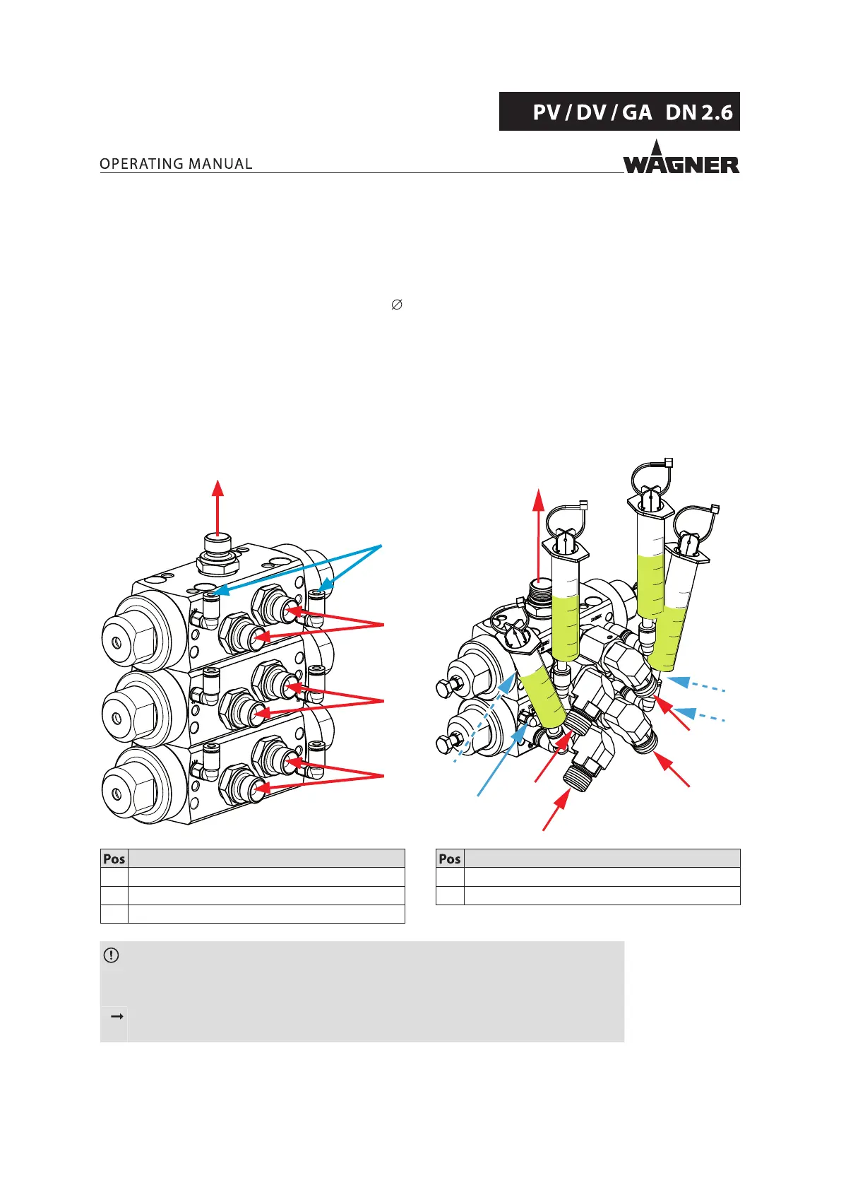
6.3.2 CONNECTIONS
Connect valves and supplementary components in accordance with the system diagram.
– Tighten all product ttings with 40 Nm; 29.5 lbs/ft.
– Control air connections: Tighten M5 threaded elbow tting with 0.16 Nm; 0.11 lbft.
– Connection of the pneumatic hoses (outside 4 mm; 0.16 inch).
– Further components:
Mount pressure gauges, pipe elbow, circulation connection, high-pressure hoses.
– Screw the completely pre-mounted valve blocks to the provided holder in
accordance with the superordinate operating manual.
Example: valve block as mixing head valve
Paint valve block/dosing valve block
PTFE valves
Dosing valve block
FFKM valves with separating agent containers
B_03993
A
A
A /
S
O
P
4
2
6
8
10
4
2
6
8
10
4
2
6
8
10
4
2
6
8
10
B_07230
P
P
B
B / S
B / S
B
P
P
O
Designation
A Product inlet (lacquer)
B Product inlet (hardener)
O Product outlet
Designation
P Control air connection
S Product inlet (ushing agent)
NOTICE
Interchange of the two components A and B!
Device damage due to hardened product.
Label device components and paint tank so that the components A and B are not
mixed up.
 Loading...