56
Weiss GmbH 03/2002
A.2 Zusatzinformationen
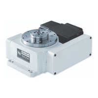
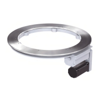
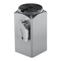
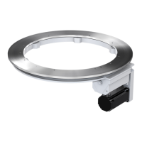
Ringrundschalttisch NR
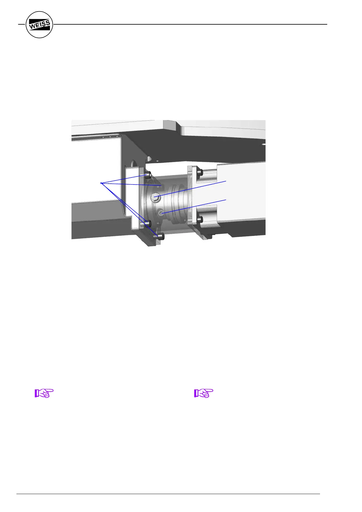
Einbau des Ringrundschalttisches NR
Zum Einbau des Ringrundschalttisches vom
Typ NR in den Montagedurchbruch der
Grundplatte (in Fig. A-4 nicht eingezeichnet)
ist der Motor inkl. der Kupplung zu
demontieren.
1. Verschlussstopfen (A) ausschrauben
2. durch die Öffnung hindurch die Klemm-
schraube (B) der Kupplung lösen
3. 4 Flanschschrauben (C) lösen
4. Motor inkl. Kupplung und Zwischenflansch
vom Antrieb abziehen
Nach Montage des Ringrundschalttisches auf
der Grundplatte kann der Antrieb wieder mon-
tiert werden.
HINWEIS ZUR
KUPPLUNGSKLEMMSCHRAUBE
Die Klemmschraube der Kupplung ist mit
einem Anzugsmoment von 80 Nm anzu-
ziehen.
A.1 Additional information
Rotary Indexing Ring NR
Mounting the Indexing Ring NR
When mounting the rotary indexing ring NR
through the assembly hole of the base plate
(not drawn in Fig. A-4) motor incl. coupling
has to be removed.
1. unscrew and remove plug (A)
2. loosen the clamp bolt (B), situated in hole
beneath plug (A)
3. remove 4 flange screws (C)
4. remove motor incl. coupling and additional
flange from drive.
After mounting the rotary indexing ring onto
the base-plate the drive can be reassembled
again.
NOTE FOR THE COUPLING CLAMP
BOLT
The torque of the coupling clamp bolt has to
be 80 Nm.
Fig. A-4
(C)
(A)
(B)
 Loading...