97-0019-01-01 11
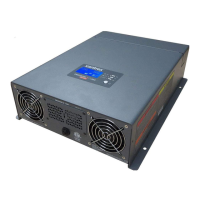
Freedom SW Inverter/Charger Mechanical Features
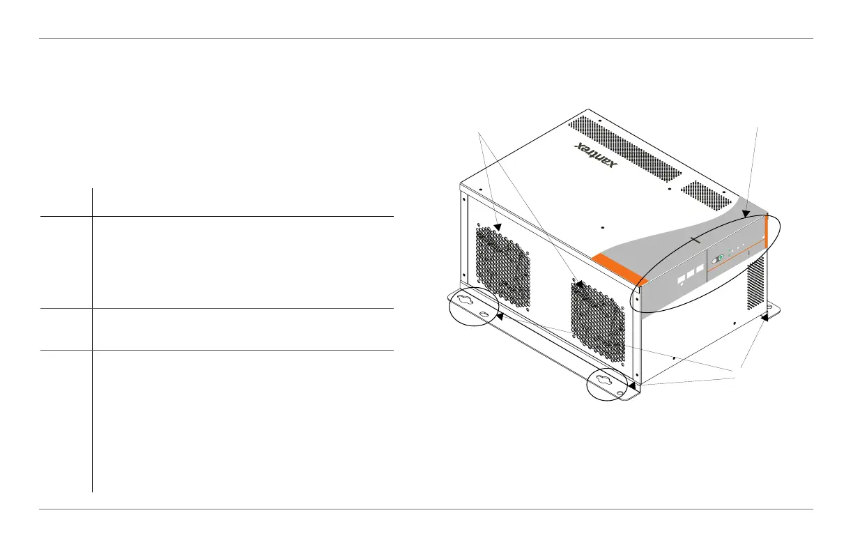
Freedom SW Front and Side Panels
Before you begin to operate the Freedom SW, review the
front panel features shown in Figure 4 and described in the
next table. A detailed view of the LEDs and buttons on the
front panel is shown in Figure 5 and described in the table
next to it.
Item Description
1 Front Panel contains the Xanbus interface ports for
connecting Xanbus-enabled devices, the
INVERTER ENABLE and CLEAR FAULT
RESET buttons, as well as various status LEDs.
See Figure 5.
2 Mounting holes are used for mounting the unit. A
total of eight holes are provided on the unit.
3 Two variable-speed cooling fans are used to cool
the unit. Fan speed control is based on internal
temperature of critical components. The two
cooling fans draw airflow into the inverter around
the transformer and power compartments of the unit
then exhaust through the other vents. Ensure at least
3 inches (76 mm) of clearance for proper
ventilation.
Figure 4 Isometric View of the Front Panel and Fans
FREEDOM SW
3012
FREEDOM
SW
3012
CLEAR FAULT
RESET
INVERTER
ENABLE
INVERTER
ENABLED
AC IN
FAULT
GEN
SUPPORT
CHARGING
WARNING
2
1
3
FSW Owners Guide.book Page 11 Tuesday, August 7, 2018 9:03 AM
 Loading...