20 2 Basic Operation
11 Front cover release lever Pulled towards you to open the front cover when replacing the print cartridge or
clearing paper jams.
12 Output tray Delivers printed output face down.
13 Extension output tray Extended to prevent output from falling off the output tray.
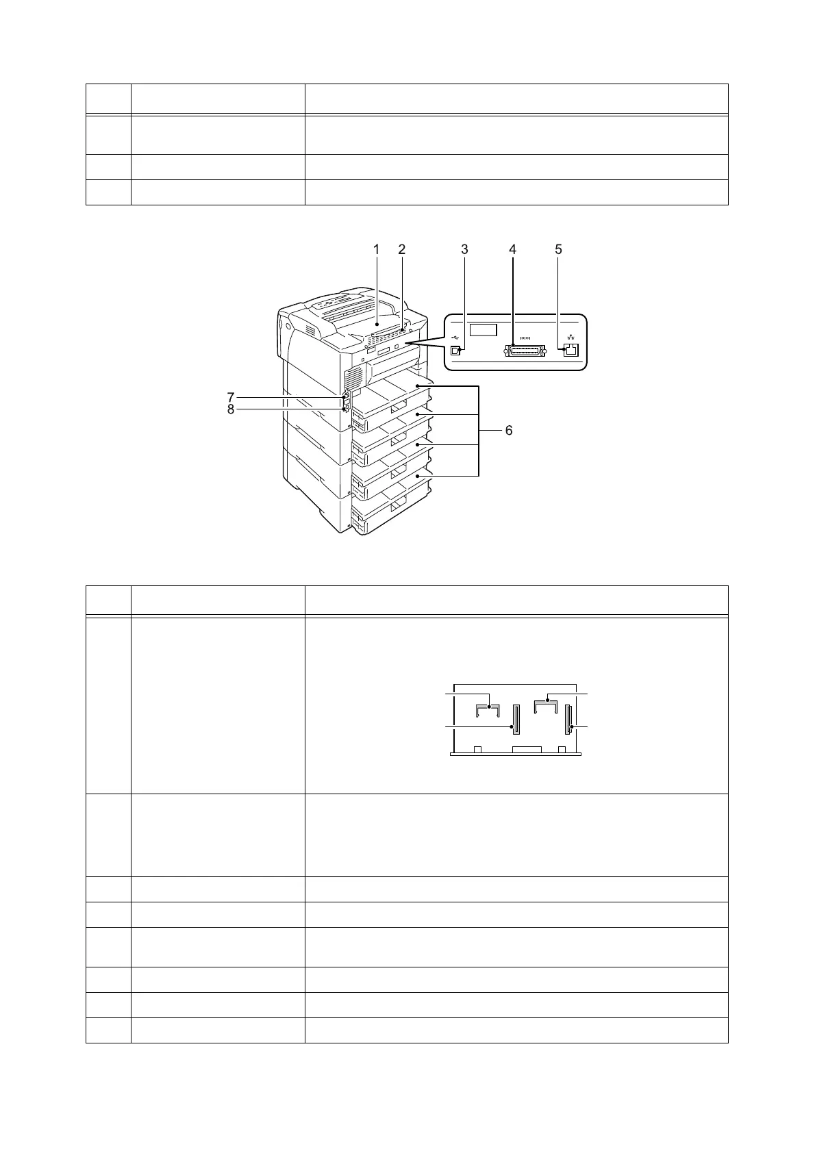
No. Name Description
Right/Rear View
No. Name Description
1 Rear cover Removed when installing the optional hard disk, memory card, or ROM.
2 Ventilation hole Releases heat to prevent the interior of the printer from overheating.
Important
• Blocking the ventilation hole causes heat build-up in the printer, which causes
the printer to malfunction.
3 USB connector Connects a USB cable to the printer.
4 Parallel connector Connects a parallel cable to the printer.
5 Network connector Connects a network cable to the printer. A network cable is used when
connecting the printer to a network.
6 Tray covers The rear covers for the paper trays.
7 Power cord connector Connects a power cord to the printer.
8 Circuit breaker Cuts off the power circuit automatically in the event of current leakage.
Slot for PostScript
ROM
Connector for
hard disk
Slot for memory card
Controller board with the rear cover and metal plate cover open
Connector for
network expansion card
 Loading...


