AC701 Evaluation Board www.xilinx.com 47
UG952 (v1.3) April 7, 2015
Feature Descriptions
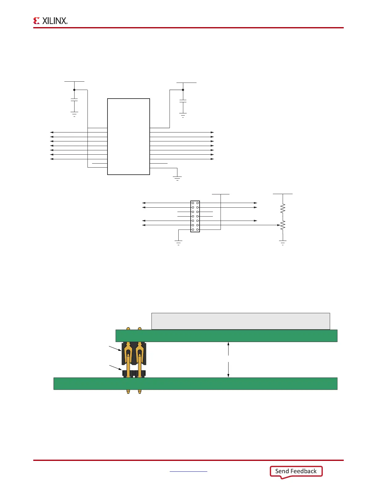
The character display runs at 5.0V and is connected to the FPGA 3.3V HP bank 14 through
a TI TXS0108E 8-bit bidirectional voltage level translator (U45).
Figure 1-27 shows the LCD
interface circuit.
The AC701 board base board uses a male Samtec MTLW-107-07-G-D-265 2x7 header (J23)
with 0.025 inch square posts on 0.100 inch centers for connecting to a Samtec
SLW-107-01-L-D female socket on the LCD display panel assembly. The LCD header
shown in
Figure 1-28.
X-Ref Target - Figure 1-27
Figure 1-27: LCD Interface Circuit
UG952_c1_25_100312
LCD Contrast
Potentiometer
LCD_RW
LCD_DB4
LCD_DB6
LCD_RS
LCD_E
NC
NC
LCD_DB5
LCD_DB7
9
87
65
43
2
10
1
12
14
11
13
LCD_VEE
GND
VCCB
B1
B2
B3
B4
B6
B7
GND
A3
A8
OE
A4
A5
A7
A6
B5
A1
A2
B8
VCCA
19
20
18
17
16
14
13
11
4
9
10
5
6
8
7
15
1
3
12
2
U45
FPGA_3V3
LCD_E_LS
LCD_RW_LS
LCD_DB4_LS
LCD_DB5_LS
LCD_DB6_LS
LCD_DB7_LS
LCD_RS_LS
NC
LCD_RS
LCD_DB7
LCD_DB6
LCD_DB5
LCD_DB4
LCD_RW
LCD_E
NC
TXS0108E 8-Bit
Bidirectional
Voltage Level
Translator
J23
GND
VCC5V0
R118
6.81kΩ
R232
2 kΩ
NC
NC
VCC5V0
C472
0.1μF 25V
X5R
GND
VCC5V0
C473
0.1μF 25V
X5R
GND
GND
X-Ref Target - Figure 1-28
Figure 1-28: LCD Header Details
UG952_c1_26_101812
LCD Display Assembly
PWA
10 mm
Low Profile Socket
Samtec SLW-107-01-L-D
Low Profile Terminal
Samtec MTLW-107-07-G-D-265

 Loading...


