64 www.xilinx.com AC701 Evaluation Board
UG952 (v1.3) April 7, 2015
Chapter 1: AC701 Evaluation Board Features
Monitoring Voltage and Current
Voltage and current monitoring and voltage control are available for the TI controlled
power rails through the Texas Instruments Fusion Digital Power Designer GUI. The two
onboard TI UCD90120A power controllers (U8 at PMBus address 101 and U9 at address
102) are wired to the same PMBus. The PMBus connector, J2, is provided for use with the
TI USB Interface Adapter PMBus pod (TI part number EVM USB-TO-GPIO) and
associated TI Fusion Digital Power Designer GUI. This is the simplest and most convenient
way to monitor the voltage and current values for the power rail listed in
Table 1-28 and
Table 1-29. For more information, see Answer Record 54022.
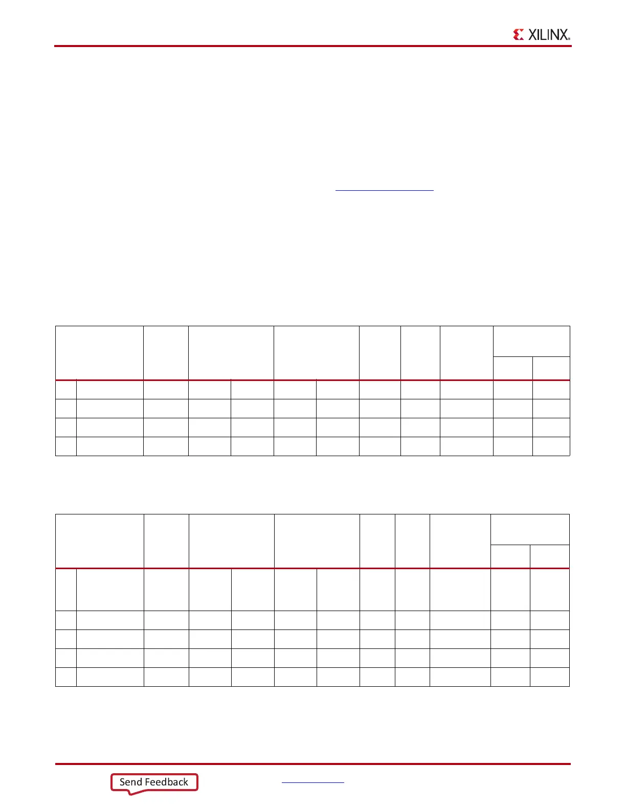
In Table 1-28 and Table 1-29 (one per controller), the Power Good (PG) On Threshold is the
set-point at or above which the particular rail is deemed good. The PG Off Threshold is the
set-point at or below which the particular rail is no longer deemed good. The controller
internally ORs these PG conditions together and drives an output PG pin High only if all
active rail PG states are good. The on and off delay parameter values are relative to when
the board power on-off slide switch SW15 is turned on and off.
Table 1-28 defines the voltage and current values for each power rail controlled by the
UCD90120A U8 controller at PMBus Address 101.
Table 1-29 defines the voltage and current values for each power rail controlled by the
UCD90120A U9 controller at PMBus Address 102.
Table 1-28: Power Rail Specifications for UCD90120A PMBus Controller U8 at Address 101
Rail
Nominal
Voltage
Power Good On Power Good Off
Turn On
Delay
(ms)
Turn
Off
Delay
(ms)
Fault
Shutdown
Slaves
Rail Turn-on
Dependencies
Rail GPI
1 VINT_1V0 1.000 0.900 –10.0% 0.850 –15.0% 0.0 15.0 Rail #2,3,4 None None
2 VAUX_1V8 1.800 1.620 –10.0% 1.530 –15.0% 10.0 5.0 Rail #1,3,4 Rail #3 None
3 VBRAM_1V0 1.000 0.900 –10.0% 0.850 –15.0% 5.0 10.0 Rail #1,2,4 Rail #1 None
4 FPGA_1V5 1.500 1.350 –10.0% 1.275 –15.0% 15.0 0.0 Rail #1,2,3 Rail #2 None
Table 1-29: Power Rail Specifications for UCD90120A PMBus Controller U9 at Address 102
Rail
Nominal
Voltage
Power Good On Power Good Off
Turn
On
Delay
(ms)
Turn
Off
Delay
(ms)
Fault
Shutdown
Slaves
Rail Turn-on
Dependencies
Rail GPI
1 VA DJ_2 V5 2.500 2.250 –10.0% 2.125 –15.0% 5.0 15.0 Rail #2,3,4,5 Rail #3
FMC_
VADJ _
ON_B
2 FPGA_1V8 1.800 1.620 –10.0% 1.530 –15.0% 10.0 10.0 Rail #1,3,4,5 None None
3 FPGA_3V3 3.300 2.970 –10.0% 2.805 –15.0% 0.0 20.0 Rail #1,2,4,5 None None
4 MGTVC_1V0 1.000 0.900 –10.0% 0.850 –15.0% 5.0 5.0 Rail #1,2,3,5 Rail #2 None
5 MGTVT_1V2 1.200 1.080 –10.0% 1.020 –15.0% 10.0 0.0 Rail #1,2,3,4 Rail #4 None

 Loading...


