Page 111FT-2000D OPERATING MANUAL
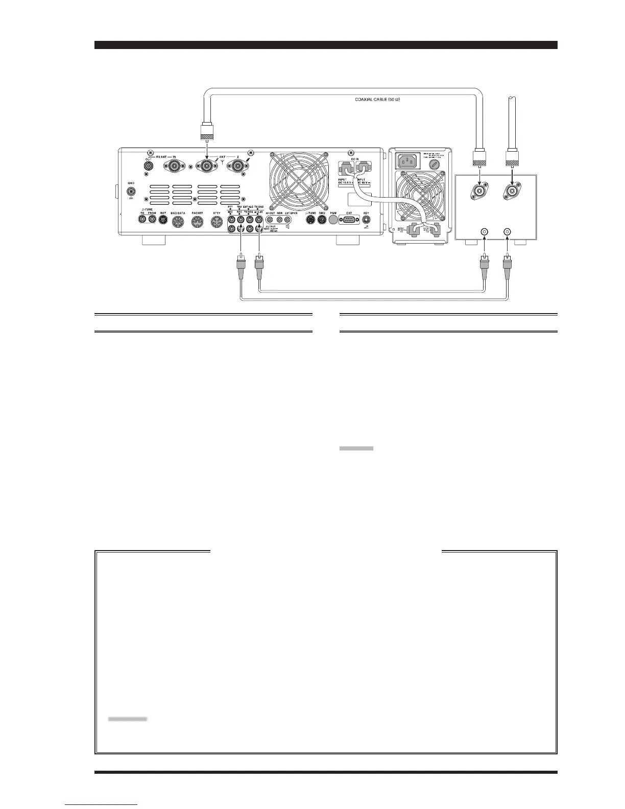
You may connect an after-market transverter to the rear panel’s TRV (Transverter) jack. The output, at 28 MHz, is approxi-
mately –10 dBm (0.1 mW) at 50 Ohms.
A
BOUT
THE
T
RANSVERTER
O
UTPUT
T
ERMINAL
SETUP
1. Press the
[
MENU
]
button to enter the Menu mode.
2. Rotate the Main Tuning Dial knob to select Menu item
“124 tun MY BAND.”
3. Rotate the
[
SUB VFO-B
]
knob to find the Menu pa-
rameter “
AU dAU d
AU dAU d
AU d” (this is the factory default setting).
4. Press the
[
ENT
]
button to change the parameter to
“ON” (a “
dd
dd
d” notation will replace the “
EE
EE
E” notation).
5. Rotate the Main Tuning Dial knob to select Menu item
“146 tGEn ETX-GND.”
6. Rotate the
[
SUB VFO-B
]
knob to set this Menu item
to “
EnAEnA
EnAEnA
EnA” to enabling the rear panel’s TX GND jack
7. Press and hold in the
[
MENU
]
button for at least two
seconds to save the new setting and exit to normal op-
eration.
OPERATION
1. Set up the frequency offset for transverter use, as de-
scribed below box.
2. Choose the “Transverter” Band with the “MY Bands”
procedures, as described on page 46. You may find the
“TRV” band between bands “1.8 MHz” and “50 MHz.”
3. Rotate the Main Tuning Dial knob to set the desired
operating frequency. Operation is basically unchanged
from normal transceiver operation.
ADVICE:
When the “TRV” mode is turned on, power output will
not be allowed to pass to the “ANT 1” or “ANT 2” main
antenna jacks. So one of these may be connected to your
transverter’s “RX” jack. Just be certain to disconnect the
transverter when returning to HF operation, as the selected
Antenna jack will now be capable of passing RF power.
Setting the Transverter Frequency Offset
You may set up the frequency display so that it shows the actual band on which your transverter is operating (instead
of the “IF” used by the transverter, which is the 28 MHz band on your FT-2000D).
Example: Setting up the FT-2000D display for use with a 144 MHz Transverter
1. Connect the 144 MHz transverter to the FT-2000D.
2. Press the
[
MENU
]
button to enter the Menu mode.
3. Rotate the Main Tuning Dial knob to select Menu item “036 GEnE TRV SET” is set to “
4444
4444
44” (the factory
default setting).
4. Rotate the
[
SUB VFO-B
]
knob so as to select “
4444
4444
44” on the display.
5. Press and hold in the
[
MENU
]
button for at least two seconds to save the new setting and exit.
The “100 MHz” digit of the frequency is not displayed, so when you are operating on 2 meters and see “45 MHz” on
the frequency readout, this indicates “145 MHz” instead.
Advice:
With the setup described above, tuning the operating range 28-29 MHz will correspond to an actual operating
frequency of 144-145 MHz, with “44-45” being displayed on the front panel of the transceiver.
Transceiver V/U ANT
TX GND RF IN
T
X
G
N
D
T
R
V
V
H
F
/
U
H
F
A
n
t
e
n
n
a
 Loading...