Page 13FT-2000D OPERATING MANUAL
ANT 1
ANT 2
ANT 3
ANT 4
REMOTE
ON
OFF
BAND DATA 1
BAND DATA 2
GND
ALC 2
ALC 1
PTT 2
PTT 1
INPUT 1
INPUT 2
CONTROL
DC48V IN
A
N
T
1
~
A
C
I
N
A
N
T
1
H
F
V
e
r
t
i
c
a
l
A
n
t
e
n
n
a
H
F
D
i
p
o
l
e
A
n
t
e
n
n
a
H
F
B
e
a
m
A
n
t
e
n
n
a
5
0
M
H
z
A
n
t
e
n
n
a
A
N
T
2
A
N
T
3
A
N
T
2
I
N
P
U
T
1
T
X
R
E
Q
E
X
T
A
L
C
B
A
N
D
D
A
T
A
B
A
N
D
-
D
A
T
A
1
B
A
N
D
-
D
A
T
A
2
G
N
D
D
C
4
8
V
I
N
C
O
N
T
R
O
L
A
L
C
1
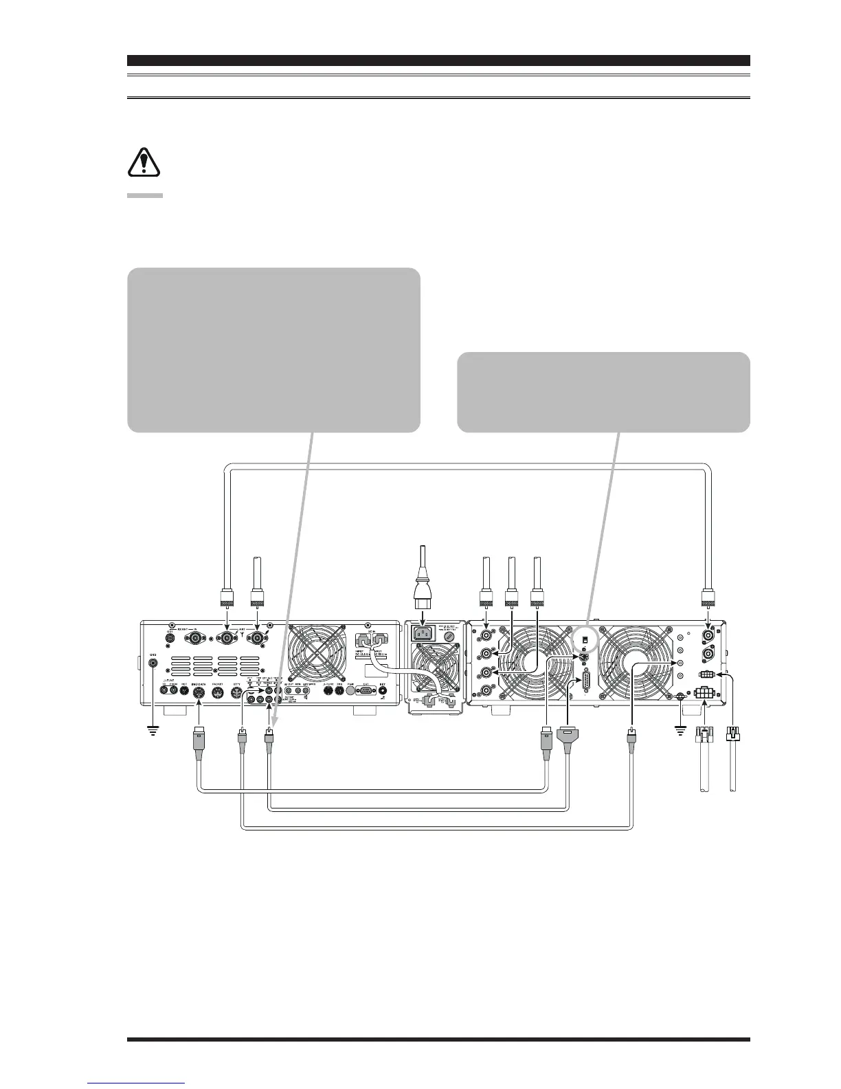
ALC CABLE
(
Supplied w/VL-1000
)
BAND DATA CABLE Supplied w/VL-1000
()
ANTENNA CABLE
(
Not Supplied
)
CONTROL CABLE
(
Supplied w/VL-1000
)
V
P
-
1
0
0
0
¾
V
P
-
1
0
0
0
¾
VL-1000 LINEAR AMPLIFIER INTERCONNECTIONS
Be sure that both the FT-2000D and VL-1000 are turned off, then follow the installation recommendations contained in
the illustration.
Set the “ATT” switch to the “ON” position on the front panel of the VL-1000. The 200-Watt power output
from the FT-2000D is far in excess of that which is required to drive the VL-1000 to its full rated output.
NOTE:
Refer to the VL-1000 Operating Manual for details regarding amplifier operation.
Do not attempt to connect or disconnect coaxial cables when your hands are wet.
INSTALLATION AND INTERCONNECTIONS
To link the FT-2000D and VL-1000 Power
switches, set the VL-1000 REMOTE switch to
the “ON” position.
About the CONTROL Cable
The VL-1000 may be operated with the FT-
2000D whether or not the CONTROL Cable is
connected; however, the CONTROL Cable al-
lows you to tune up the amplifier automatically
by just pressing the [F SET] or [TUNE] key on
the VL-1000 to transmit a carrier for tuning pur-
poses.
 Loading...