5-13
Engine control unit and component
Using the digital tester
The electrical technical data applies to the
measurements taken using the Yamaha rec-
ommended tester.
The resistance values shown are the values
taken before the engine is started. The actual
resistance may vary depending on the envi-
ronmental conditions and ambient tempera-
ture.
The input voltage changes depending on the
battery voltage.
If the tester probe cannot be inserted into the
coupler, prepare a test lead suitable for the
measurement.
Engine control unit and
component
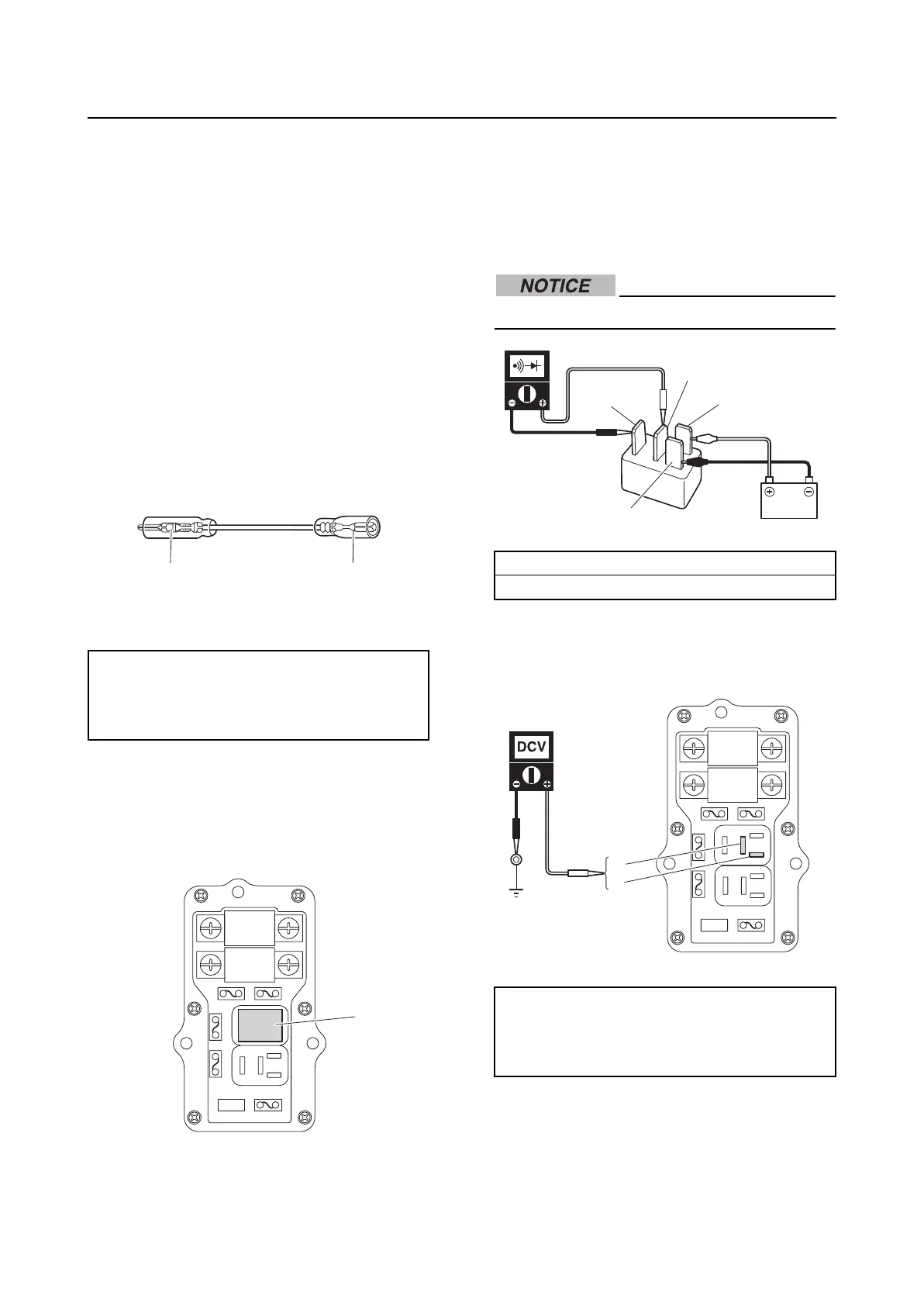
Checking the main relay
1. Remove the main relay “1”.
2. Connect the positive battery lead to the
terminal “a”, connect the negative battery
lead to the terminal “b”, and then check
for continuity between the terminals “c”,
and “d”. Replace the relay if out of speci-
fication.
Do not reverse the battery leads.
3. Measure the input voltage between the
terminal “a” and ground, and the terminal
“b” and ground.
4. Turn the engine start switch to ON, and
then measure the input voltage between
terminals “a” and “b”.
Test lead:
Terminal, male “1”: 9E212-10303
Terminal, female “2”:
(commercially available)
12
1
Relay terminals continuity:
Terminal “c”–Terminal “d”
Main relay input voltage:
Terminal “a”–Ground
Terminal “b”–Ground
12 V (battery voltage)
a
b
d
c
a
b

 Loading...