8-25
Drive shaft and lower case (regular rotation model)
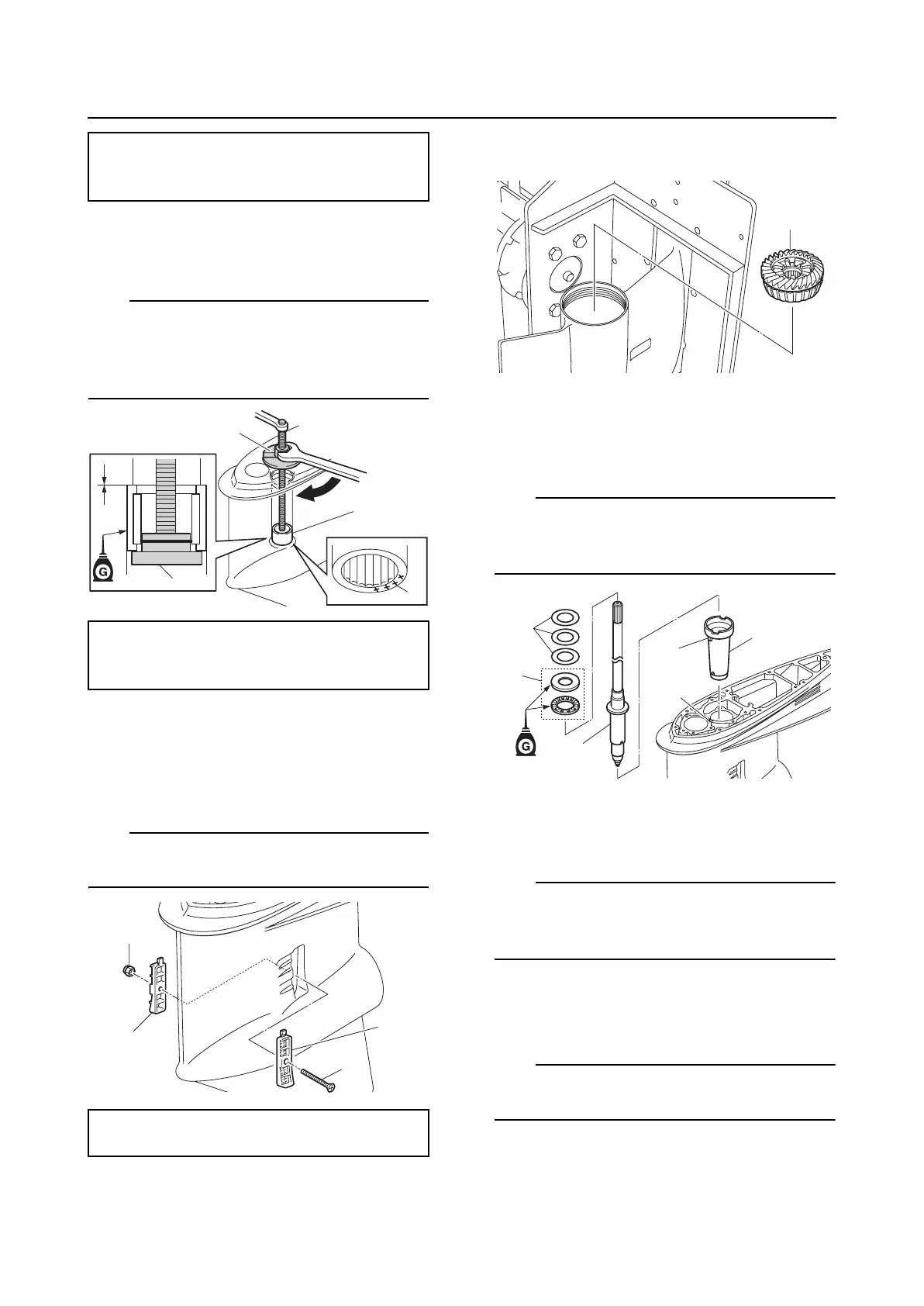
4. Install a new needle bearing “1” in the
lower case.
TIP:
• Make sure to face the bearing identification
mark “a” on the needle bearing toward the
pinion.
• The needle bearing contains 18 rollers.
5. Install the water inlet covers “1” and “2”,
nut “3”, and water inlet cover screw “4”,
and then tighten the water inlet cover
screw “4” to the specified torque.
TIP:
After installing the water inlet covers, make
sure that there is no rattling.
Installing the drive shaft
1. Install the forward gear assembly “1”.
2. Install the sleeve “1”, drive shaft “2”,
thrust bearing “3”, and original pinion
shims “4”.
TIP:
Make sure that the protrusion “a” on the
sleeve “1” is aligned with the slot “b” in the
lower case.
3. Install the pinion and pinion nut tempo-
rarily.
TIP:
When installing the pinion, lift up the drive
shaft slightly and align the splines on the
drive shaft with the splines on the pinion.
4. Install the drive shaft housing “1” and
cover “2” into the lower case.
TIP:
Make sure to face the cutout “a” in the drive
shaft housing “1” forward.
Driver rod LL “1”: 90890-06605
Bearing outer race attachment “2”:
90890-06619
Ball bearing attachment “2”: 90890-06633
Bearing outer race puller assembly “3”:
90890-06523
Water inlet cover screw “4”:
1 N·m (0.1 kgf·m, 0.7 ft·lb)
1
2
a
3
1
2
3
4
1
1
2
3
4
a
b

 Loading...