5-22
Ignition unit and component
0
1
2
3
4
5
6
7
8
9
10
A
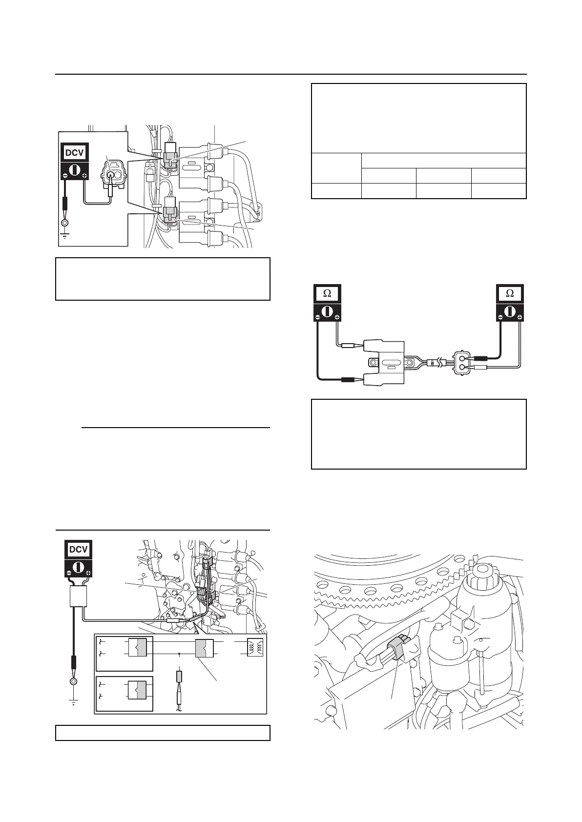
2. Turn the engine start switch to ON, and
then measure the input voltage at the
ignition coil coupler terminal and ground.
3. Turn the engine start switch to OFF.
4. Connect the ignition coil coupler “a”.
5. Connect the special service tool “1”, and
then measure the ignition coil output
peak voltage.
TIP:
• When measuring the ignition coil output
peak voltage under the cranking (unloaded)
condition, disconnect all fuel injector cou-
plers to prevent the engine from starting.
• Measure the output peak voltage of ignition
coil (for cylinders #2 and #3) in the same
way.
6. Disconnect the special service tool and
spark plug wires from the ignition coils.
7. Measure the ignition coil resistance.
8. Connect the spark plug wires and ignition
coil couplers.
Checking the pulser coil
1. Disconnect the pulser coil coupler “a”.
2. Connect the special service tool “1”.
Ignition coil input voltage:
Red/Yellow (R/Y)–Ground
12 V (battery voltage)
Test harness (2 pins) “1”: 90890-06792
a
b
R/Y
1
B/W
B/W
R
R/Y
B/W
B/O
1
a
R/Y
A
B
Ignition coil output peak voltage:
#1, #4 “A”:
Black/Orange (B/O)–Ground
#2, #3 “B”:
Black/White (B/W)–Ground
r/min
Loaded
Cranking 1500 3500
DC V 210.0 260.0 270.0
Ignition coil resistance:
Primary coil “A”:
1.530–2.070 Ω at 20 °C (68 °F)
Secondary coil “B”:
12.50–16.91 kΩ at 20 °C (68 °F)
B
A
a

 Loading...