7-9
Power unit assembly
0
1
2
3
4
5
6
7
8
9
10
A
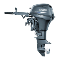
16. Install the lifting harnesses to the engine
hangers “1”.
17. Suspend the power unit.
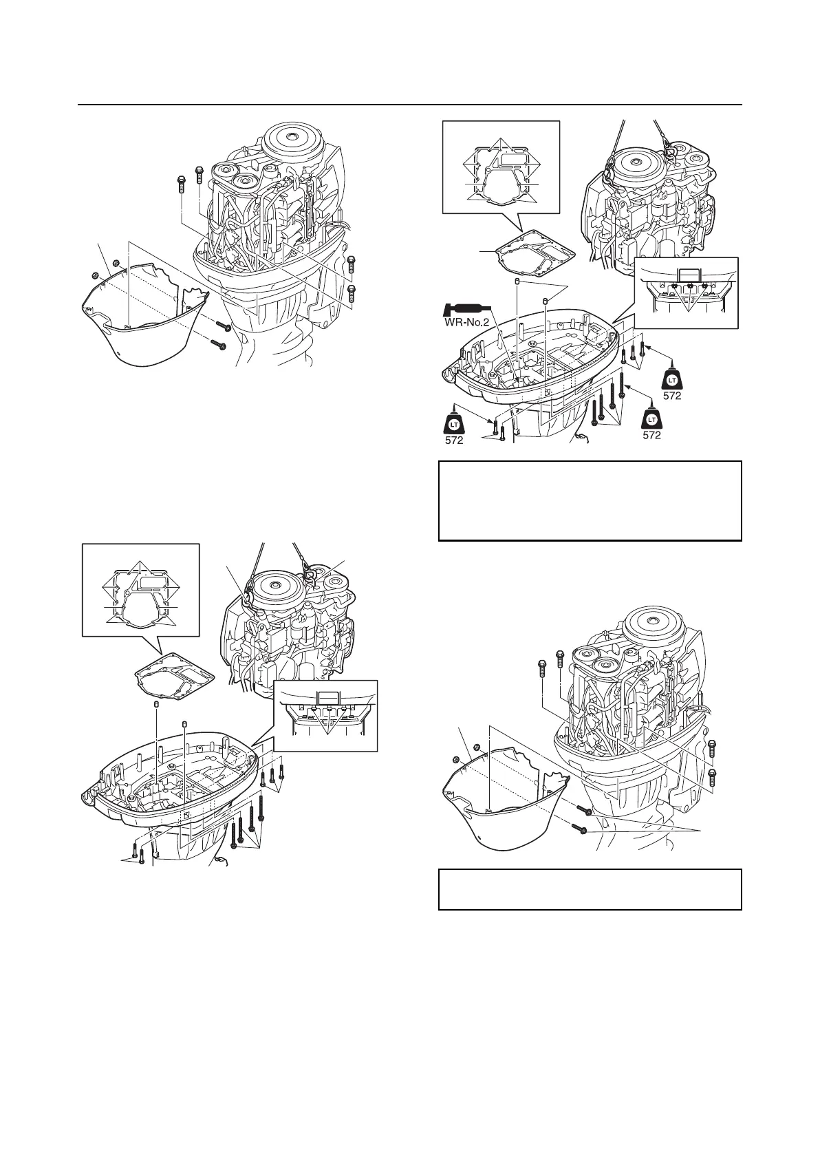
18. Remove the power unit mounting bolts
“2”, “3”, and “4”, and then remove the
power unit.
Installing the power unit
1. Clean the power unit mating surface, and
then install the dowels “1” and a new gas-
ket “2”.
2. Install the power unit, and then tighten
the power unit mounting bolts “3”, “4”,
and “5” to the specified torque.
3. Install the apron “1”, and then tighten the
apron screw “2” to the specified torque.
4. Connect the flushing hose “1”, and then
fasten it using the plastic tie “2”.
1
1
1
2
2
2
3
33
3
3
4
4
4
Power unit mounting bolt (M8) “3”:
20 N·m (2.0 kgf·m, 14.8 ft·lb)
Power unit mounting bolts (M10) “4” and
“5”: 42 N·m (4.2 kgf·m, 31.0 ft·lb)
Apron screw “2”:
4 N·m (0.4 kgf·m, 3.0 ft·lb)
3
3
3
4
44
4
4
5
2
1
5
5
1
2

 Loading...